MaruduinoでXBeeを使ってみる。マイコン、パソコン無しで制御 #xbee [アプリケーション]
※今回もXBeeシリーズ1でやっとります。
※動画を作成していただきました。貼り付けておきます。
前回のIO出力では制御側にはArduino(Maruduino)を使っていました。実はXBeeはこの様な外部の制御なんたらを必要とせずに遠方のモジュールの出力を制御する事ができます。
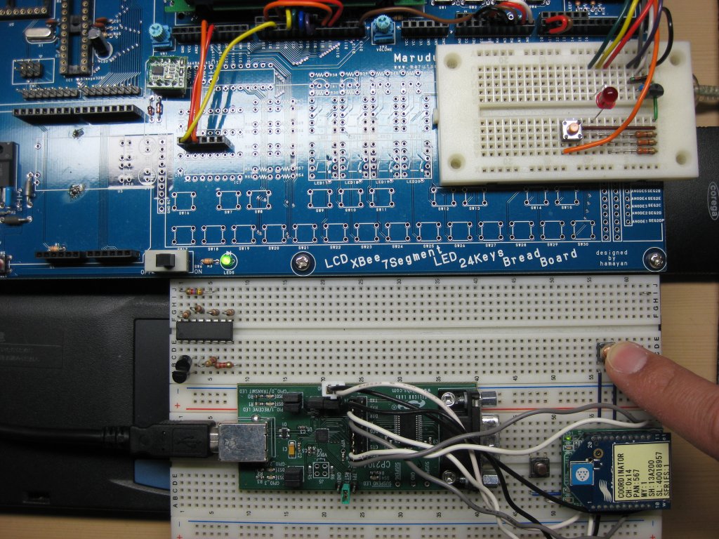
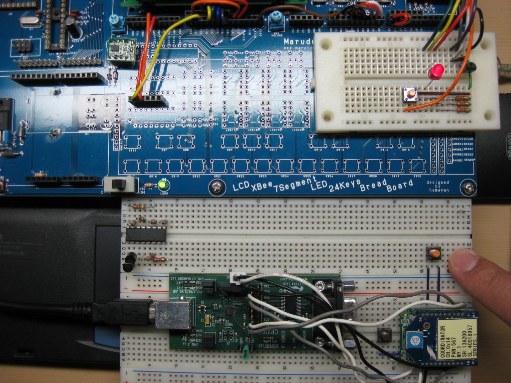
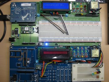
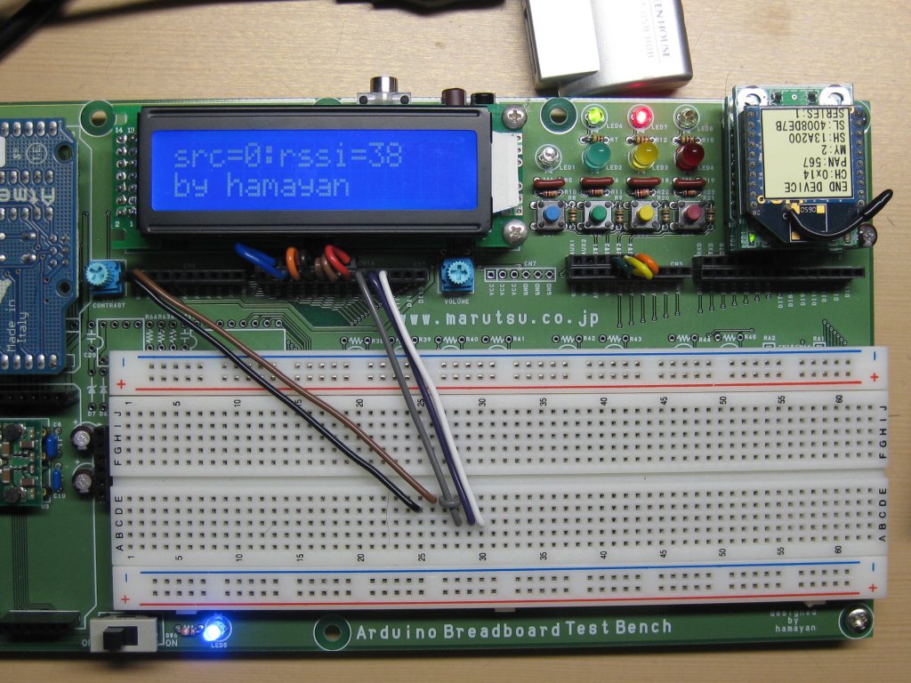
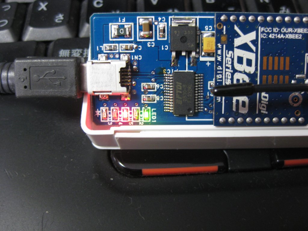
写真を見ると判りますが、下はUSBシリアル変換基板に接続されたXBeeのモジュールで、USBシリアルはコンフィギュレーション完了後は単にXBeeアダプターへ電源を供給しているにすぎません。
また、上のMaruduinoにはArduinoもAVRも搭載されていない事が判ります。
指の先にタクトスイッチがありますが、離すとMaruduino上のブレッドボードの赤色LEDが点灯し、押すと消灯します。
タクトスイッチは制御側XBeeのD1に接続されています。またLEDは遠方のD1に接続されています。
この制御のやり方の肝は、D1なら相手のD1に、D2なら相手のD2に状態が反映される事で、例えばD1の状態を相手のD2に反映すると言った事はできません。また、制御側のD1の状態が"High"なら相手も”High”、制御側が"Low"であれば相手も"Low"であり、ロジックの反転はできませんので、必要ならば外部にインバーターを用意します。
先の例で言えば制御側のD1は入力設定されていますが、ポートのプルアップが有効となっていますので、タクトスイッチから指を離すと状態は"High"ですし、スイッチを押せば"Low"となります。
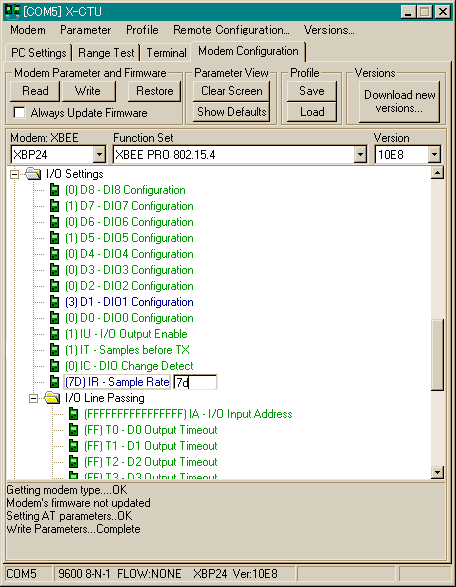
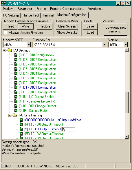
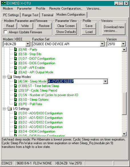
X-CTUのコンフィギュレーションを見てみましょう。上のX-CTUのキャプチャは制御側、下は遠方側です。
制御側:
まずDH=0、DL=相手の16bitアドレスとして制御の送り先を指定しておきます。チャネルやPAN ID等は適宜に設定しておいてください。
D1=3として入力にします。IU=1、IT=1、IR=0x7Dとしています。つまり125ms置きにサンプリングデータのパケットを送信する訳です。なお時間は遠方側で説明します。
遠方側:
チャネルやPAN ID、16bitアドレスなどは適宜設定しておきます。
APIモードに設定します。
D1=4とし、標準は"Low"出力設定です。
I/O Line Passingを展開してI/O Input Addressを設定します。16bitのユニキャストアドレスを指定した場合は該当するアドレス、0xFFFFとした場合は全ての受信したパケットを受け入れます。64bit全て1であれば制御パケットは拒否されます。
T1=5として非標準状態がアサートされる継続時間を設定します。16進表記であり、入力した値×100msとなっているので500ms間は非標準状態が継続します。先ほどパケットの送信間隔を125msとしたのは時間切れとなる500msに十分余裕を持たせたからです。
このタイマーは受け入れ可能なパケットを受信する度にクリアされ、カウントが再開します。なお、タイマーをOFFする設定はありませんでした。
ZigBeeのプロファイルにはホーム照明プロファイルがありますが、XBeeのこの設定を使って、手元のスイッチで天井の電灯の制御をすると言ったホーム照明プロファイルっぽいものができますね。
![[XBee 2個+書込基板+解説書]キット付き 超お手軽無線モジュールXBee: すぐにつながる!どこまでも広がる!「※超お手軽無線モジュールXBee2012年 03月号[雑誌] が入っています」 (トライアルシリーズ)](https://images-fe.ssl-images-amazon.com/images/I/51jtT9QX9BL._SL160_.jpg "[XBee 2個+書込基板+解説書]キット付き 超お手軽無線モジュールXBee: すぐにつながる!どこまでも広がる!「※超お手軽無線モジュールXBee2012年 03月号[雑誌] が入っています」 (トライアルシリーズ)")
![超お手軽無線モジュールXBee 2012年 03月号 [雑誌] 「※[XBee 2個+書込基板+解説書]キット付き 超お手軽無線モジュールXBee[単行本]に入っている解説書と同じものです」 (トライアルシリーズ)](https://images-fe.ssl-images-amazon.com/images/I/51ZFtEKvS8L._SL160_.jpg "超お手軽無線モジュールXBee 2012年 03月号 [雑誌] 「※[XBee 2個+書込基板+解説書]キット付き 超お手軽無線モジュールXBee[単行本]に入っている解説書と同じものです」 (トライアルシリーズ)")

![トランジスタ技術 SPECIAL (スペシャル) 2011年 01月号 [雑誌]](https://images-fe.ssl-images-amazon.com/images/I/5178YN0YPiL._SL160_.jpg "トランジスタ技術 SPECIAL (スペシャル) 2011年 01月号 [雑誌]")
※動画を作成していただきました。貼り付けておきます。
 |
 |
 |
 |
写真を見ると判りますが、下はUSBシリアル変換基板に接続されたXBeeのモジュールで、USBシリアルはコンフィギュレーション完了後は単にXBeeアダプターへ電源を供給しているにすぎません。
また、上のMaruduinoにはArduinoもAVRも搭載されていない事が判ります。
指の先にタクトスイッチがありますが、離すとMaruduino上のブレッドボードの赤色LEDが点灯し、押すと消灯します。
タクトスイッチは制御側XBeeのD1に接続されています。またLEDは遠方のD1に接続されています。
この制御のやり方の肝は、D1なら相手のD1に、D2なら相手のD2に状態が反映される事で、例えばD1の状態を相手のD2に反映すると言った事はできません。また、制御側のD1の状態が"High"なら相手も”High”、制御側が"Low"であれば相手も"Low"であり、ロジックの反転はできませんので、必要ならば外部にインバーターを用意します。
先の例で言えば制御側のD1は入力設定されていますが、ポートのプルアップが有効となっていますので、タクトスイッチから指を離すと状態は"High"ですし、スイッチを押せば"Low"となります。
X-CTUのコンフィギュレーションを見てみましょう。上のX-CTUのキャプチャは制御側、下は遠方側です。
制御側:
まずDH=0、DL=相手の16bitアドレスとして制御の送り先を指定しておきます。チャネルやPAN ID等は適宜に設定しておいてください。
D1=3として入力にします。IU=1、IT=1、IR=0x7Dとしています。つまり125ms置きにサンプリングデータのパケットを送信する訳です。なお時間は遠方側で説明します。
遠方側:
チャネルやPAN ID、16bitアドレスなどは適宜設定しておきます。
APIモードに設定します。
D1=4とし、標準は"Low"出力設定です。
I/O Line Passingを展開してI/O Input Addressを設定します。16bitのユニキャストアドレスを指定した場合は該当するアドレス、0xFFFFとした場合は全ての受信したパケットを受け入れます。64bit全て1であれば制御パケットは拒否されます。
T1=5として非標準状態がアサートされる継続時間を設定します。16進表記であり、入力した値×100msとなっているので500ms間は非標準状態が継続します。先ほどパケットの送信間隔を125msとしたのは時間切れとなる500msに十分余裕を持たせたからです。
このタイマーは受け入れ可能なパケットを受信する度にクリアされ、カウントが再開します。なお、タイマーをOFFする設定はありませんでした。
ZigBeeのプロファイルにはホーム照明プロファイルがありますが、XBeeのこの設定を使って、手元のスイッチで天井の電灯の制御をすると言ったホーム照明プロファイルっぽいものができますね。
- 作者: 濱原 和明 佐藤 尚一 ほか著
- 出版社/メーカー: CQ出版
- 発売日: 2012/02/27
- メディア: 単行本
- 作者: 濱原 和明
- 出版社/メーカー: CQ出版
- 発売日: 2012/02/27
- メディア: 雑誌
ITRONプログラミング入門―H8マイコンとHOSで始める組み込み開発
- 作者: 濱原 和明
- 出版社/メーカー: オーム社
- 発売日: 2005/04/25
- メディア: 単行本
トランジスタ技術 SPECIAL (スペシャル) 2011年 01月号 [雑誌]
- 作者:
- 出版社/メーカー: CQ出版
- 発売日: 2010/12/28
- メディア: 雑誌
MaruduinoでXBeeを使ってみる。主にRemote ATコマンドでIO出力。 [アプリケーション]
※スケッチを書き込む時はXBeeを外すか、接続を全て外してから行ってください。
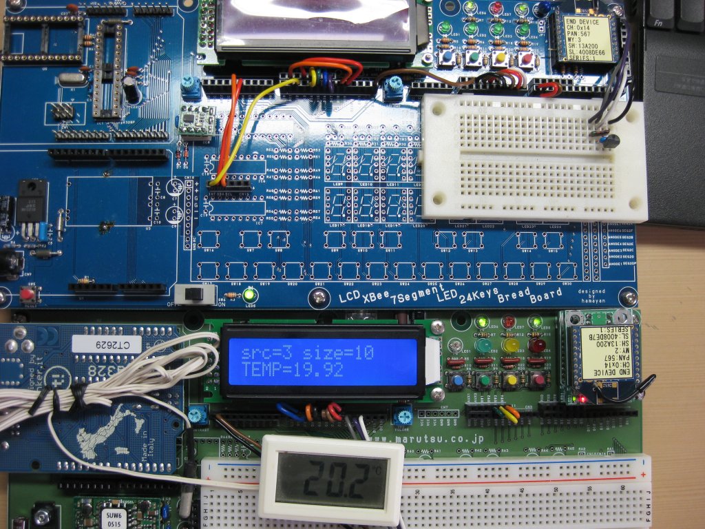
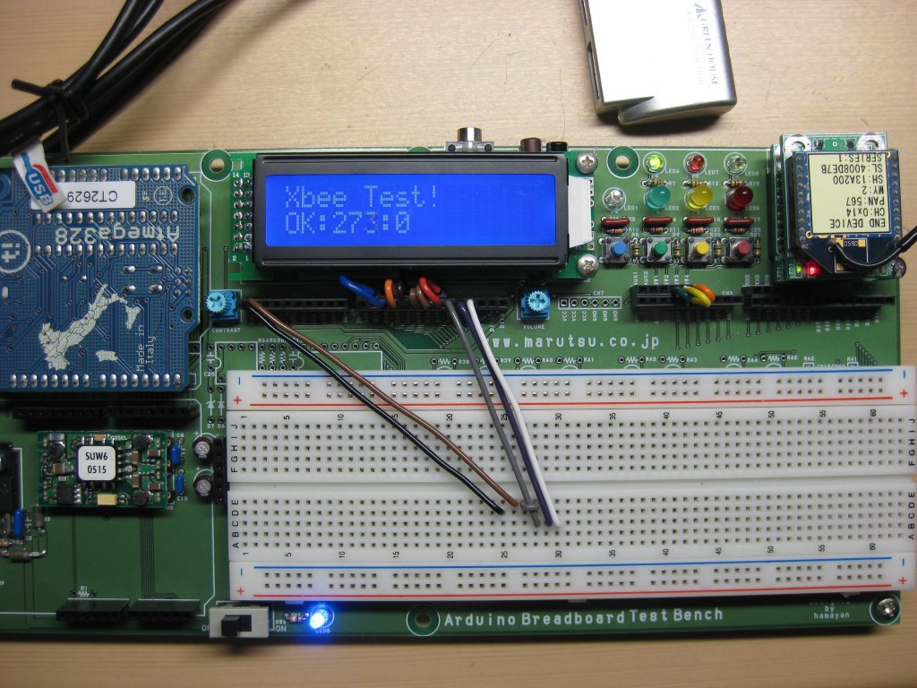
※写真の様に2個のXBeeの内、一つはADC0を温度センサーであるLM61CIZに接続しています。この時温度センサー側のMaruduino自体は単にXBeeに電源を供給しているのみで、特にプログラムが走ってはいません。あくまでも温度センサー側のXBeeはスタンドアローンで動かしています。
前回同様、いままでのページを参照の上、ご覧ください。
http://maruduino.blog.so-net.ne.jp/2011-01-05-1
http://maruduino.blog.so-net.ne.jp/2011-01-05
http://maruduino.blog.so-net.ne.jp/2011-01-04
前回はIO Samplingで温度データの取り込みを行いましたが、今度は逆にポート出力を行います。
使うのはRemote ATコマンドです。事前にターゲット(Remote側)のXBeeのDIO1、DIO2、DIO3を出力に設定しておきます。いや、今回の場合はしなくても大丈夫です。Remote ATコマンドで出力の状態を変化させるのは、実質的に毎回XBeeのコンフィギュレーションを行っている様なものですから。
事前の準備として、Remote側のMaruduinoのCN20端子のAD1~AD3にLEDを接続しておきます。
コントロール側のMaruduinoはSW2~SW4の状態を取り込みます。つまりこのSW2~SW4が押されていればRemote側のLEDが点灯、離されていれば消灯を行う実に簡単なアプリケーションとなっています。
")
※写真の様に2個のXBeeの内、一つはADC0を温度センサーであるLM61CIZに接続しています。この時温度センサー側のMaruduino自体は単にXBeeに電源を供給しているのみで、特にプログラムが走ってはいません。あくまでも温度センサー側のXBeeはスタンドアローンで動かしています。

前回同様、いままでのページを参照の上、ご覧ください。
http://maruduino.blog.so-net.ne.jp/2011-01-05-1
http://maruduino.blog.so-net.ne.jp/2011-01-05
http://maruduino.blog.so-net.ne.jp/2011-01-04
前回はIO Samplingで温度データの取り込みを行いましたが、今度は逆にポート出力を行います。
使うのはRemote ATコマンドです。事前にターゲット(Remote側)のXBeeのDIO1、DIO2、DIO3を出力に設定しておきます。いや、今回の場合はしなくても大丈夫です。Remote ATコマンドで出力の状態を変化させるのは、実質的に毎回XBeeのコンフィギュレーションを行っている様なものですから。
事前の準備として、Remote側のMaruduinoのCN20端子のAD1~AD3にLEDを接続しておきます。
コントロール側のMaruduinoはSW2~SW4の状態を取り込みます。つまりこのSW2~SW4が押されていればRemote側のLEDが点灯、離されていれば消灯を行う実に簡単なアプリケーションとなっています。
/*
  LiquidCrystal Library - Hello World

 Demonstrates the use a 16x2 LCD display.  The LiquidCrystal
 library works with all LCD displays that are compatible with the
 Hitachi HD44780 driver. There are many of them out there, and you
 can usually tell them by the 16-pin interface.

 This sketch prints "Hello World!" to the LCD
 and shows the time.

  The circuit:
 * LCD RS pin to digital DI2
 * LCD Enable pin to digital Di3
 * LCD D4 pin to digital DI4
 * LCD D5 pin to digital DI5
 * LCD D6 pin to digital DI6
 * LCD D7 pin to digital DI7
 * LCD R/W pin to ground
 * 10K resistor:
 * ends to +5V and ground
 * wiper to LCD VO pin (pin 3)

 Library originally added 18 Apr 2008
 by David A. Mellis
 library modified 5 Jul 2009
 by Limor Fried (http://www.ladyada.net)
 example added 9 Jul 2009
 by Tom Igoe
 modified 22 Nov 2010
 by Tom Igoe

 This example code is in the public domain.

 http://www.arduino.cc/en/Tutorial/LiquidCrystal
 */

/**
 * Copyright (c) 2009 Andrew Rapp. All rights reserved.
 *
 * This file is part of XBee-Arduino.
 *
 * XBee-Arduino is free software: you can redistribute it and/or modify
 * it under the terms of the GNU General Public License as published by
 * the Free Software Foundation, either version 3 of the License, or
 * (at your option) any later version.
 *
 * XBee-Arduino is distributed in the hope that it will be useful,
 * but WITHOUT ANY WARRANTY; without even the implied warranty of
 * MERCHANTABILITY or FITNESS FOR A PARTICULAR PURPOSE.  See the
 * GNU General Public License for more details.
 *
 * You should have received a copy of the GNU General Public License
 * along with XBee-Arduino.  If not, see <http://www.gnu.org/licenses/>.
 */


// include the library code:
#include <LiquidCrystal.h>
#include <XBee.h>
#include <stdlib.h>
#include <string.h>
/*************************************************************************/
/* defines                                                               */
/*************************************************************************/
#if 0
#define  DI13     2
#define  DI12     3
#define  DI11     4
#define  DI10     5
#define  DI9      6
#define  DI8      7
#define  DI7      8
#define  DI6      9
#define  DI5      10
#define  DI4      11
#define  DI3      12
#define  DI2      13
#define  DI1
#define  DI0
#else
#define  DI13     13
#define  DI12     12
#define  DI11     11
#define  DI10     10
#define  DI9      9
#define  DI8      8
#define  DI7      7
#define  DI6      6
#define  DI5      5
#define  DI4      4
#define  DI3      3
#define  DI2      2
#define  DI1      1
#define  DI0      0
#endif

#define  AN0      14
#define  AN1      15
#define  AN2      16
#define  AN3      17
#define  AN4      18
#define  AN5      19

// initialize the library with the numbers of the interface pins
LiquidCrystal lcd(DI2, DI3, DI4, DI5, DI6, DI7);
XBee xbee = XBee();

uint8_t d1Cmd[] = { 'D', '1' };
uint8_t d1Value[1];  /*0x04 is low, 0x05 is high*/
uint8_t d2Cmd[] = { 'D', '2' };
uint8_t d2Value[1];  /*0x04 is low, 0x05 is high*/
uint8_t d3Cmd[] = { 'D', '3' };
uint8_t d3Value[1];  /*0x04 is low, 0x05 is high*/

// DH + DL of your remote radio
XBeeAddress64 remoteAddress = XBeeAddress64(0x0013a200, 0x4008de66);
// Create a remote AT request command
RemoteAtCommandRequest remoteAtRequest
  = RemoteAtCommandRequest(remoteAddress, d1Cmd, d1Value, sizeof(d1Value));
// Create a Remote AT response object
RemoteAtCommandResponse remoteAtResponse = RemoteAtCommandResponse();

boolean an[3][3] =
{
  {false,false,false,},
  {false,false,false,},
  {false,false,false,},
};

void setup()
{
  lcd.begin(16, 2);
  lcd.print("Xbee Test!");
  xbee.begin(9600);
  pinMode( AN5, INPUT );
  pinMode( AN4, INPUT );
  pinMode( AN3, INPUT );

 // When powered on, XBee radios require a few seconds to start up
 // and join the network.
 // During this time, any packets sent to the radio are ignored.
 // Series 2 radios send a modem status packet on startup.

 // it took about 4 seconds for mine to return modem status.
 // In my experience, series 1 radios take a bit longer to associate.
 // Of course if the radio has been powered on for some time before the sketch runs,
 // you can safely remove this delay.
 // Or if you both commands are not successful, try increasing the delay.

 delay(5000);
}

void loop()
{
  an[0][0] = an[0][1];an[0][1] = an[0][2];
  an[0][2] = ( digitalRead( AN5 ) == HIGH ) ? true : false;

  an[1][0] = an[1][1];an[1][1] = an[1][2];
  an[1][2] = ( digitalRead( AN4 ) == HIGH ) ? true : false;

  an[2][0] = an[2][1];an[2][1] = an[2][2];
  an[2][2] = ( digitalRead( AN3 ) == HIGH ) ? true : false;

  remoteAtRequest.setCommand(d1Cmd);
  remoteAtRequest.setCommandValue(d1Value);
  remoteAtRequest.setCommandValueLength(sizeof(d1Value));
  if( an[0][0] == false && an[0][1] == false && an[0][2] == true )
  {
    d1Value[0] = 0x5;  /*0x04 is low, 0x05 is high*/
    sendRemoteAtCommand();
  }
  else if( an[0][0] == true && an[0][1] == true && an[0][2] == false )
  {
    d1Value[0] = 0x4;  /*0x04 is low, 0x05 is high*/
    sendRemoteAtCommand();
  }
  else {}

  remoteAtRequest.setCommand(d2Cmd);
  remoteAtRequest.setCommandValue(d2Value);
  remoteAtRequest.setCommandValueLength(sizeof(d2Value));
  if( an[1][0] == false && an[1][1] == false && an[1][2] == true )
  {
    d2Value[0] = 0x5;  /*0x04 is low, 0x05 is high*/
    sendRemoteAtCommand();
  }
  else if( an[1][0] == true && an[1][1] == true && an[1][2] == false )
  {
    d2Value[0] = 0x4;  /*0x04 is low, 0x05 is high*/
    sendRemoteAtCommand();
  }
  else {}

  remoteAtRequest.setCommand(d3Cmd);
  remoteAtRequest.setCommandValue(d3Value);
  remoteAtRequest.setCommandValueLength(sizeof(d3Value));
  if( an[2][0] == false && an[2][1] == false && an[2][2] == true )
  {
    d3Value[0] = 0x5;  /*0x04 is low, 0x05 is high*/
    sendRemoteAtCommand();
  }
  else if( an[2][0] == true && an[2][1] == true && an[2][2] == false )
  {
    d3Value[0] = 0x4;  /*0x04 is low, 0x05 is high*/
    sendRemoteAtCommand();
  }
  else {}

  delay(50);
}

void sendRemoteAtCommand()
{
  // send the command
  xbee.send(remoteAtRequest);

  // wait up to 5 seconds for the status response
  if (xbee.readPacket(5000))
  {
    // got a response!

    // should be an AT command response
    if (xbee.getResponse().getApiId() == REMOTE_AT_COMMAND_RESPONSE)
    {
      xbee.getResponse().getRemoteAtCommandResponse(remoteAtResponse);

      if (remoteAtResponse.isOk())
      {
        lcd.clear();
        lcd.print("Command ");
        lcd.print(remoteAtResponse.getCommand()[0]);
        lcd.print(remoteAtResponse.getCommand()[1]);
        lcd.print(" OK.");

        if(remoteAtResponse.getValueLength() > 0)
        {
          lcd.setCursor(0, 1);
          lcd.print("len:");
          lcd.print(remoteAtResponse.getValueLength(), DEC);
          lcd.print(" val:");

          for (int i = 0; i < remoteAtResponse.getValueLength(); i++)
          {
            lcd.print(remoteAtResponse.getValue()[i], HEX);
            lcd.print(" ");
          }
        }
      }
      else
      {
        lcd.clear();
        lcd.print("Command returned");
        lcd.setCursor(0, 1);
        lcd.print("ERROR CODE:");
        lcd.print(remoteAtResponse.getStatus(), HEX);
      }
    }
    else
    {
      lcd.clear();
      lcd.print("Error response");
      lcd.setCursor(0, 1);
      lcd.print("ID:");
      lcd.print(xbee.getResponse().getApiId(), HEX);
    }
  }
  else
  {
    // remote at command failed
    if (xbee.getResponse().isError())
    {
      lcd.clear();
      lcd.print("Remote AT Error");
      lcd.setCursor(0, 1);
      lcd.print("CODE:");
      lcd.print(xbee.getResponse().getErrorCode());
    }
    else
    {
      lcd.clear();
      lcd.print("No response");
      lcd.setCursor(0, 1);
      lcd.print(" from radio");
    }
  }
}
- 作者: 鄭 立
- 出版社/メーカー: リックテレコム
- 発売日: 2006/02
- メディア: 単行本
MaruduinoでXBeeを使ってみる。主にIO Sampling。 [アプリケーション]
※スケッチを書き込む時はXBeeを外すか、接続を全て外してから行ってください。
※写真の様に2個のXBeeの内、一つはADC0を温度センサーであるLM61CIZに接続しています。この時温度センサー側のMaruduino自体は単にXBeeに電源を供給しているのみで、特にプログラムが走ってはいません。あくまでも温度センサー側のXBeeはスタンドアローンで動かしています。
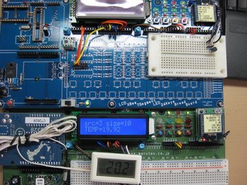
MaruduinoのXBeeの横にあるCN20からはXBeeの幾つかの端子と、3.3V電源出力、GND、VREFが引き出せますので、ブレッドボードなどに回路を組んで実験を行うことができます。
XBeeと温度センサーとの接続および設定に関してはこのページを参考としてください。
http://hamayan.blog.so-net.ne.jp/2010-10-17-1
例によってxbee-arduinoライブラリのサンプルを元にアプリケーションを作成していますので、以下のページもご参照ください。
http://maruduino.blog.so-net.ne.jp/2011-01-05
http://maruduino.blog.so-net.ne.jp/2011-01-04
![トランジスタ技術 (Transistor Gijutsu) 2010年 11月号 [雑誌]](https://images-fe.ssl-images-amazon.com/images/I/51auJcqDHhL._SL160_.jpg "トランジスタ技術 (Transistor Gijutsu) 2010年 11月号 [雑誌]")
※写真の様に2個のXBeeの内、一つはADC0を温度センサーであるLM61CIZに接続しています。この時温度センサー側のMaruduino自体は単にXBeeに電源を供給しているのみで、特にプログラムが走ってはいません。あくまでも温度センサー側のXBeeはスタンドアローンで動かしています。
MaruduinoのXBeeの横にあるCN20からはXBeeの幾つかの端子と、3.3V電源出力、GND、VREFが引き出せますので、ブレッドボードなどに回路を組んで実験を行うことができます。
XBeeと温度センサーとの接続および設定に関してはこのページを参考としてください。
http://hamayan.blog.so-net.ne.jp/2010-10-17-1
例によってxbee-arduinoライブラリのサンプルを元にアプリケーションを作成していますので、以下のページもご参照ください。
http://maruduino.blog.so-net.ne.jp/2011-01-05
http://maruduino.blog.so-net.ne.jp/2011-01-04
/*
  LiquidCrystal Library - Hello World

 Demonstrates the use a 16x2 LCD display.  The LiquidCrystal
 library works with all LCD displays that are compatible with the
 Hitachi HD44780 driver. There are many of them out there, and you
 can usually tell them by the 16-pin interface.

 This sketch prints "Hello World!" to the LCD
 and shows the time.

  The circuit:
 * LCD RS pin to digital DI2
 * LCD Enable pin to digital Di3
 * LCD D4 pin to digital DI4
 * LCD D5 pin to digital DI5
 * LCD D6 pin to digital DI6
 * LCD D7 pin to digital DI7
 * LCD R/W pin to ground
 * 10K resistor:
 * ends to +5V and ground
 * wiper to LCD VO pin (pin 3)

 Library originally added 18 Apr 2008
 by David A. Mellis
 library modified 5 Jul 2009
 by Limor Fried (http://www.ladyada.net)
 example added 9 Jul 2009
 by Tom Igoe
 modified 22 Nov 2010
 by Tom Igoe

 This example code is in the public domain.

 http://www.arduino.cc/en/Tutorial/LiquidCrystal
 */

/**
 * Copyright (c) 2009 Andrew Rapp. All rights reserved.
 *
 * This file is part of XBee-Arduino.
 *
 * XBee-Arduino is free software: you can redistribute it and/or modify
 * it under the terms of the GNU General Public License as published by
 * the Free Software Foundation, either version 3 of the License, or
 * (at your option) any later version.
 *
 * XBee-Arduino is distributed in the hope that it will be useful,
 * but WITHOUT ANY WARRANTY; without even the implied warranty of
 * MERCHANTABILITY or FITNESS FOR A PARTICULAR PURPOSE.  See the
 * GNU General Public License for more details.
 *
 * You should have received a copy of the GNU General Public License
 * along with XBee-Arduino.  If not, see <http://www.gnu.org/licenses/>.
 */


// include the library code:
#include <LiquidCrystal.h>
#include <XBee.h>
#include <stdlib.h>
#include <string.h>
/*************************************************************************/
/* defines                                                               */
/*************************************************************************/
#if 0
#define  DI13     2
#define  DI12     3
#define  DI11     4
#define  DI10     5
#define  DI9      6
#define  DI8      7
#define  DI7      8
#define  DI6      9
#define  DI5      10
#define  DI4      11
#define  DI3      12
#define  DI2      13
#define  DI1
#define  DI0
#else
#define  DI13     13
#define  DI12     12
#define  DI11     11
#define  DI10     10
#define  DI9      9
#define  DI8      8
#define  DI7      7
#define  DI6      6
#define  DI5      5
#define  DI4      4
#define  DI3      3
#define  DI2      2
#define  DI1      1
#define  DI0      0
#endif

// initialize the library with the numbers of the interface pins
LiquidCrystal lcd(DI2, DI3, DI4, DI5, DI6, DI7);
XBee xbee = XBee();
Rx16IoSampleResponse ioSample = Rx16IoSampleResponse();

void setup()
{
  lcd.begin(16, 2);
  lcd.print("Xbee Test!");
  xbee.begin(9600);
}

void loop()
{
  xbee.readPacket();

  if (xbee.getResponse().isAvailable())
  {
    // got something
    if(xbee.getResponse().getApiId() == RX_16_IO_RESPONSE)
    {
      xbee.getResponse().getRx16IoSampleResponse(ioSample);
      lcd.clear();
      lcd.print("src=");
      lcd.print(ioSample.getRemoteAddress16(), HEX);
      lcd.print(" size=");
      lcd.print(ioSample.getSampleSize(), DEC);

      unsigned long adc = 0;
      for(int i = 0; i < ioSample.getSampleSize(); i++)
      {
        adc += ioSample.getAnalog(0,i);
      }
      adc /= ioSample.getSampleSize();
      lcd.setCursor(0, 1);
      float temper = ((adc * 3.3 / 1024) - 0.6) / 0.01;
      lcd.print("TEMP=");
      lcd.print(temper);
    }
    else
    {
      lcd.clear();
      lcd.print("Expected I/O Sample,");
      lcd.setCursor(0, 1);
      lcd.print("but got ");
      lcd.print(xbee.getResponse().getApiId(), HEX);
    }
  }
  else if(xbee.getResponse().isError())
  {
    lcd.clear();
    lcd.print("Error reading packet.");
    lcd.setCursor(0, 1);
    lcd.print("Error code:");
    lcd.print(xbee.getResponse().getErrorCode(),HEX);
  }
}
トランジスタ技術 (Transistor Gijutsu) 2010年 11月号 [雑誌]
- 作者:
- 出版社/メーカー: CQ出版
- 発売日: 2010/10/09
- メディア: 雑誌
MaruduinoでXBeeを使ってみる。主に受信。 [アプリケーション]
※スケッチを書き込む時はXBeeを外すか、接続を全て外してから行ってください。
※2個のXBeeが必要です。また、Maruduinoと対向する側はPCに接続し、X-CTUでモニターします。
前回は送信でしたので、今回はさらっと受信してみます。
Xbeeの設定は前回と同様ですが、PC側のXBeeの送り先16bitアドレスにはMaruduinoに搭載されているXbeeの16bitアドレスを設定しておきます。
前回へのリンク
http://maruduino.blog.so-net.ne.jp/2011-01-04
X-CTUのターミナル画面でASSEMBLE PACKETボタンを押して文字単位での送信ではなく、文字列単位の送信を行える様にしています。
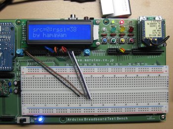
MaruduinoのLCD画面には送信元アドレスとRSSI値、それに受信した文字列を表示します。
※2個のXBeeが必要です。また、Maruduinoと対向する側はPCに接続し、X-CTUでモニターします。
前回は送信でしたので、今回はさらっと受信してみます。
Xbeeの設定は前回と同様ですが、PC側のXBeeの送り先16bitアドレスにはMaruduinoに搭載されているXbeeの16bitアドレスを設定しておきます。
前回へのリンク
http://maruduino.blog.so-net.ne.jp/2011-01-04
X-CTUのターミナル画面でASSEMBLE PACKETボタンを押して文字単位での送信ではなく、文字列単位の送信を行える様にしています。
MaruduinoのLCD画面には送信元アドレスとRSSI値、それに受信した文字列を表示します。
/*
  LiquidCrystal Library - Hello World

 Demonstrates the use a 16x2 LCD display.  The LiquidCrystal
 library works with all LCD displays that are compatible with the
 Hitachi HD44780 driver. There are many of them out there, and you
 can usually tell them by the 16-pin interface.

 This sketch prints "Hello World!" to the LCD
 and shows the time.

  The circuit:
 * LCD RS pin to digital DI2
 * LCD Enable pin to digital Di3
 * LCD D4 pin to digital DI4
 * LCD D5 pin to digital DI5
 * LCD D6 pin to digital DI6
 * LCD D7 pin to digital DI7
 * LCD R/W pin to ground
 * 10K resistor:
 * ends to +5V and ground
 * wiper to LCD VO pin (pin 3)

 Library originally added 18 Apr 2008
 by David A. Mellis
 library modified 5 Jul 2009
 by Limor Fried (http://www.ladyada.net)
 example added 9 Jul 2009
 by Tom Igoe
 modified 22 Nov 2010
 by Tom Igoe

 This example code is in the public domain.

 http://www.arduino.cc/en/Tutorial/LiquidCrystal
 */

/**
 * Copyright (c) 2009 Andrew Rapp. All rights reserved.
 *
 * This file is part of XBee-Arduino.
 *
 * XBee-Arduino is free software: you can redistribute it and/or modify
 * it under the terms of the GNU General Public License as published by
 * the Free Software Foundation, either version 3 of the License, or
 * (at your option) any later version.
 *
 * XBee-Arduino is distributed in the hope that it will be useful,
 * but WITHOUT ANY WARRANTY; without even the implied warranty of
 * MERCHANTABILITY or FITNESS FOR A PARTICULAR PURPOSE.  See the
 * GNU General Public License for more details.
 *
 * You should have received a copy of the GNU General Public License
 * along with XBee-Arduino.  If not, see <http://www.gnu.org/licenses/>.
 */


// include the library code:
#include <LiquidCrystal.h>
#include <XBee.h>
#include <stdlib.h>
#include <string.h>
/*************************************************************************/
/* defines                                                               */
/*************************************************************************/
#if 0
#define  DI13     2
#define  DI12     3
#define  DI11     4
#define  DI10     5
#define  DI9      6
#define  DI8      7
#define  DI7      8
#define  DI6      9
#define  DI5      10
#define  DI4      11
#define  DI3      12
#define  DI2      13
#define  DI1
#define  DI0
#else
#define  DI13     13
#define  DI12     12
#define  DI11     11
#define  DI10     10
#define  DI9      9
#define  DI8      8
#define  DI7      7
#define  DI6      6
#define  DI5      5
#define  DI4      4
#define  DI3      3
#define  DI2      2
#define  DI1      1
#define  DI0      0
#endif

// initialize the library with the numbers of the interface pins
LiquidCrystal lcd(DI2, DI3, DI4, DI5, DI6, DI7);
XBee xbee = XBee();
XBeeResponse response = XBeeResponse();
// create reusable response objects for responses we expect to handle
Rx16Response rx16 = Rx16Response();
Rx64Response rx64 = Rx64Response();

uint8_t option = 0;
uint8_t data = 0;

void setup()
{
  lcd.begin(16, 2);
  lcd.print("Xbee Test!");
  xbee.begin(9600);
}

void loop()
{
  xbee.readPacket();

  if(xbee.getResponse().isAvailable())
  {
    // got something
    if(xbee.getResponse().getApiId() == RX_16_RESPONSE
     || xbee.getResponse().getApiId() == RX_64_RESPONSE )
    {
      // got a rx packet
      if(xbee.getResponse().getApiId() == RX_16_RESPONSE)
      {
        xbee.getResponse().getRx16Response(rx16);
        option = rx16.getOption();
//        data = rx16.getData(0);
      }
      else
      {
        xbee.getResponse().getRx64Response(rx64);
        option = rx64.getOption();
//        data = rx64.getData(0);
      }

      uint8_t len = xbee.getResponse().getFrameDataLength();
      char *buf = (char *)malloc( (size_t)len );
      memcpy( buf, xbee.getResponse().getFrameData(), len );

      lcd.clear();
      lcd.print("src=");
      int src = (buf[0] << 8) | buf[1];
      lcd.print(src,HEX);
      lcd.print(":rssi=");
      int rssi = (int)buf[2];
      lcd.print(rssi,DEC);

      lcd.setCursor(0, 1);
      for( char *ptr = buf + 4; len > 4; len-- )
      {
        lcd.write( *ptr++ );
      }
      free( buf );
    }
    else
    {
      // not something we were expecting
    }
  }
}
ITRONプログラミング入門―H8マイコンとHOSで始める組み込み開発
- 作者: 濱原 和明
- 出版社/メーカー: オーム社
- 発売日: 2005/04/25
- メディア: 単行本
MaruduinoでXBeeを使ってみる。主に送信。 [アプリケーション]
※スケッチを書き込む時はXBeeを外すか、接続を全て外してから行ってください。
※2個のXBeeが必要です。また、Maruduinoと対向する側はPCに接続し、X-CTUでモニターします。

XBeeの使用例です。
これはLiquidCrystalライブラリとxbee-arduinoライブラリを使用しています。
http://code.google.com/p/xbee-arduino/
xbee-arduinoライブラリのインストールは適宜サイトを読んで行って下さい。
Xbeeはシリーズ1を使っています。上記ライブラリを使用するためにはX-CTUでMaruduinoに搭載する側のXBeeにAPI2モードを設定しておきます。端末通信速度はデフォルトの9600bpsに設定しています。使用チャンネルやPAN ID、16bitアドレスなどは適宜設定してください。
相手側はAPIモードでも良いのですが、今回はATモードにしてあります。ターミナル画面でSHOW HEXを設定しておくと、数字がインクリメントされるデータが送られてくるのが判ります。
")
※2個のXBeeが必要です。また、Maruduinoと対向する側はPCに接続し、X-CTUでモニターします。
XBeeの使用例です。
これはLiquidCrystalライブラリとxbee-arduinoライブラリを使用しています。
http://code.google.com/p/xbee-arduino/
xbee-arduinoライブラリのインストールは適宜サイトを読んで行って下さい。
Xbeeはシリーズ1を使っています。上記ライブラリを使用するためにはX-CTUでMaruduinoに搭載する側のXBeeにAPI2モードを設定しておきます。端末通信速度はデフォルトの9600bpsに設定しています。使用チャンネルやPAN ID、16bitアドレスなどは適宜設定してください。
相手側はAPIモードでも良いのですが、今回はATモードにしてあります。ターミナル画面でSHOW HEXを設定しておくと、数字がインクリメントされるデータが送られてくるのが判ります。
/*
  LiquidCrystal Library - Hello World

 Demonstrates the use a 16x2 LCD display.  The LiquidCrystal
 library works with all LCD displays that are compatible with the
 Hitachi HD44780 driver. There are many of them out there, and you
 can usually tell them by the 16-pin interface.

 This sketch prints "Hello World!" to the LCD
 and shows the time.

  The circuit:
 * LCD RS pin to digital DI2
 * LCD Enable pin to digital Di3
 * LCD D4 pin to digital DI4
 * LCD D5 pin to digital DI5
 * LCD D6 pin to digital DI6
 * LCD D7 pin to digital DI7
 * LCD R/W pin to ground
 * 10K resistor:
 * ends to +5V and ground
 * wiper to LCD VO pin (pin 3)

 Library originally added 18 Apr 2008
 by David A. Mellis
 library modified 5 Jul 2009
 by Limor Fried (http://www.ladyada.net)
 example added 9 Jul 2009
 by Tom Igoe
 modified 22 Nov 2010
 by Tom Igoe

 This example code is in the public domain.

 http://www.arduino.cc/en/Tutorial/LiquidCrystal
 */

/**
 * Copyright (c) 2009 Andrew Rapp. All rights reserved.
 *
 * This file is part of XBee-Arduino.
 *
 * XBee-Arduino is free software: you can redistribute it and/or modify
 * it under the terms of the GNU General Public License as published by
 * the Free Software Foundation, either version 3 of the License, or
 * (at your option) any later version.
 *
 * XBee-Arduino is distributed in the hope that it will be useful,
 * but WITHOUT ANY WARRANTY; without even the implied warranty of
 * MERCHANTABILITY or FITNESS FOR A PARTICULAR PURPOSE.  See the
 * GNU General Public License for more details.
 *
 * You should have received a copy of the GNU General Public License
 * along with XBee-Arduino.  If not, see <http://www.gnu.org/licenses/>.
 */


// include the library code:
#include <LiquidCrystal.h>
#include <XBee.h>
/*************************************************************************/
/* defines                                                               */
/*************************************************************************/
#if 0
#define  DI13     2
#define  DI12     3
#define  DI11     4
#define  DI10     5
#define  DI9      6
#define  DI8      7
#define  DI7      8
#define  DI6      9
#define  DI5      10
#define  DI4      11
#define  DI3      12
#define  DI2      13
#define  DI1
#define  DI0
#else
#define  DI13     13
#define  DI12     12
#define  DI11     11
#define  DI10     10
#define  DI9      9
#define  DI8      8
#define  DI7      7
#define  DI6      6
#define  DI5      5
#define  DI4      4
#define  DI3      3
#define  DI2      2
#define  DI1      1
#define  DI0      0
#endif

// initialize the library with the numbers of the interface pins
LiquidCrystal lcd(DI2, DI3, DI4, DI5, DI6, DI7);
XBee xbee = XBee();
unsigned long start = millis();
uint8_t payload[] = { 0, 0 };
Tx16Request tx = Tx16Request(0, payload, sizeof(payload));
TxStatusResponse txStatus = TxStatusResponse();
int suc_cnt,flt_cnt,loop_cnt;

void setup()
{
  lcd.begin(16, 2);
  lcd.print("Xbee Test!");
  xbee.begin(9600);
}

void loop()
{
  // start transmitting after a startup delay.  Note: this will rollover to 0 eventually so not best way to handle
  if (millis() - start > 15000)
  {
    payload[0] = loop_cnt >> 8 & 0xff;
    payload[1] = loop_cnt++ & 0xff;
    xbee.send(tx);
  }

  // after sending a tx request, we expect a status response
  // wait up to 5 seconds for the status response
  if (xbee.readPacket(5000))
  {
    lcd.setCursor(0, 1);
             //0123456789012345
    lcd.print("                ");
    // got a response!
    // should be a znet tx status
    if (xbee.getResponse().getApiId() == TX_STATUS_RESPONSE)
    {
      xbee.getResponse().getZBTxStatusResponse(txStatus);
      // get the delivery status, the fifth byte
      if (txStatus.getStatus() == SUCCESS)
      {
        // success.  time to celebrate
        lcd.setCursor(0, 1);
        lcd.print("OK:");
        lcd.print(++suc_cnt);lcd.print(":");lcd.print(flt_cnt);
      }
      else
      {
        // the remote XBee did not receive our packet. is it powered on?
        lcd.setCursor(0, 1);
        lcd.print("NG:");
        lcd.print(suc_cnt);lcd.print(":");lcd.print(++flt_cnt);
      }
    }
  }
  else
  {
    // local XBee did not provide a timely TX Status Response -- should not happen
    lcd.setCursor(0, 1);
    lcd.print("TRANSMIT ERR");
  }
  delay(200);
}
Prototyping Lab ―「作りながら考える」ためのArduino実践レシピ (Make:PROJECTS)
- 作者: 小林 茂
- 出版社/メーカー: オライリージャパン
- 発売日: 2010/05/27
- メディア: 大型本
フリスクサイズ XBeeインタフェースボードの製作、配付 MTM06にて [アプリケーション]
 作りました。
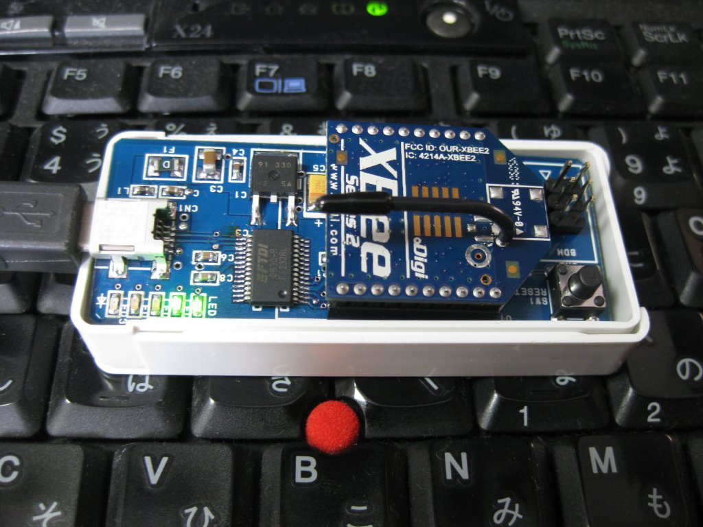
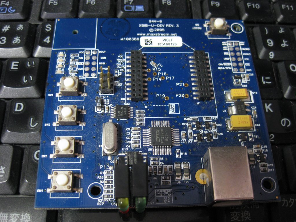
通常は下の写真の様な純正のUSBインタフェース基板を使うのですが、まあちょっとでかいですし、ハンドリングも悪いのでフリスクサイズの基板を作成しました。
ただし元々純正基板にあった機能をこのサイズに突っ込むのは難しいので、幾つかの機能は削除しています。ですが、実用上は問題無いでしょう。
 削ってしまった機能は、まずRSSI表示がありません。これにあと3個もLEDを追加しても見るかどうか、、、。
DIN、DOUTのモニターLEDは有りますが、点灯時間を延長する回路は搭載していません。
本来USBの電源利用は、PC側から大きな電流使って良いよ!と許可が出るまでスタンバイに入っているのですが、まあ回路を載せられない事も無いのですが、部品増えますし、面倒なのでUSBに接続したらいきなりフルパワーになっています。
 ここだけは削れなかった機能としてはDTR、RTS、CTSのサポートとリセットスイッチとBDMコネクターです。
DTRはUSBインタフェースボード上でXBeeをスリープモードにした場合、SLEEP_RQの制御に使いますし、RTS、CTSはファームの更新時には大量の更新データを通信でやり取りしますので、その際に必要です。
 リセットスイッチはXBeeのモデムタイプを変更したりファームを更新する際には必ず必要です。それ以外にもCYCLIC SLEEPに設定した場合、コンフィギュレーションを変更しようにもXBeeがSLEEPに入っている場合はREADやWRITEが上手く行かない時が有ります。そんな時はREADやWRITEボタンを押した直後にこのリセットスイッチを押せば当然XBeeは起動からスタートしますので、すんなり通ります。
BDMコネクターはProgrammable XBeeのファームウエアをいじったり、その上で動作するアプリケーションのデバックには必須です。
このUSBインタフェースボードはMTM06にて実費(250円)で配付いたします。MTM06で配付するのは基板とドキュメントのみですが、事前に部品セット込みで予約いただければ、当日部品セットも用意いたしたいと思います。半田ごて等の工具も用意しておきますので、その場で組み立てOKです(笑)。
ITRONプログラミング入門―H8マイコンとHOSで始める組み込み開発
- 作者: 濱原 和明
- 出版社/メーカー: オーム社
- 発売日: 2005/04/25
- メディア: 単行本
Prototyping Lab ―「作りながら考える」ためのArduino実践レシピ
- 作者: 小林 茂
- 出版社/メーカー: オライリージャパン
- 発売日: 2010/05/27
- メディア: 大型本
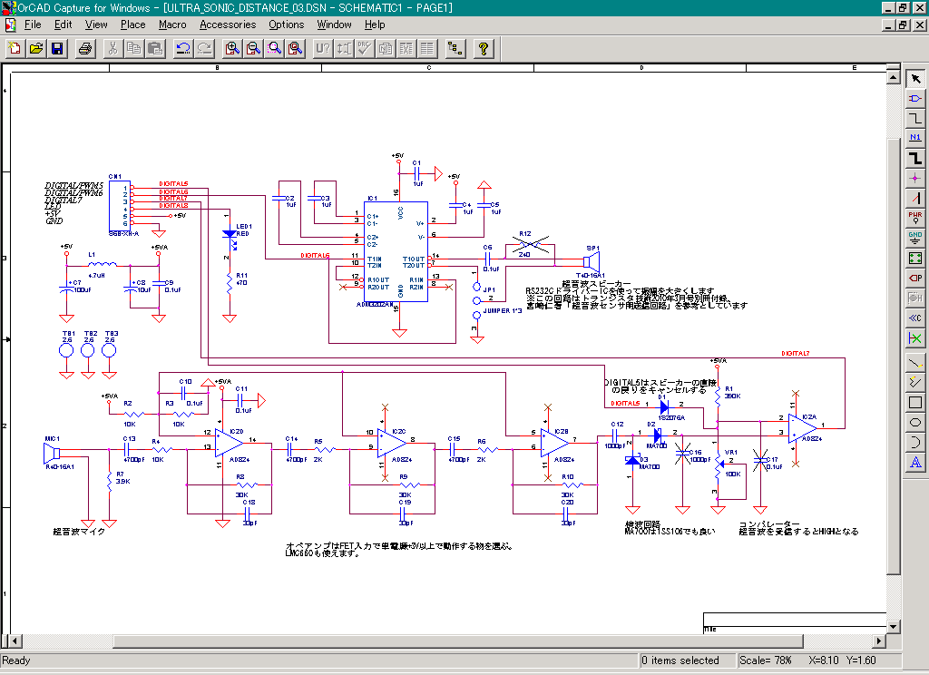
超音波距離計測モジュール Ultrasonic Distanceの配付をMTM06辺りで行います。 #mtm06 [アプリケーション]
※欲しい方は事前に連絡ください。量産と言っても数に限りがあります。売り切れごめん(笑)です。
※秋月でニセラのT4016A1、R4016A1の扱いが無くなったと思いきや、今度は台湾メーカーでそっくりの品の扱いが始まったようです。
http://akizukidenshi.com/catalog/g/gI-00120/
購入して同様に使えるのか試してみます。
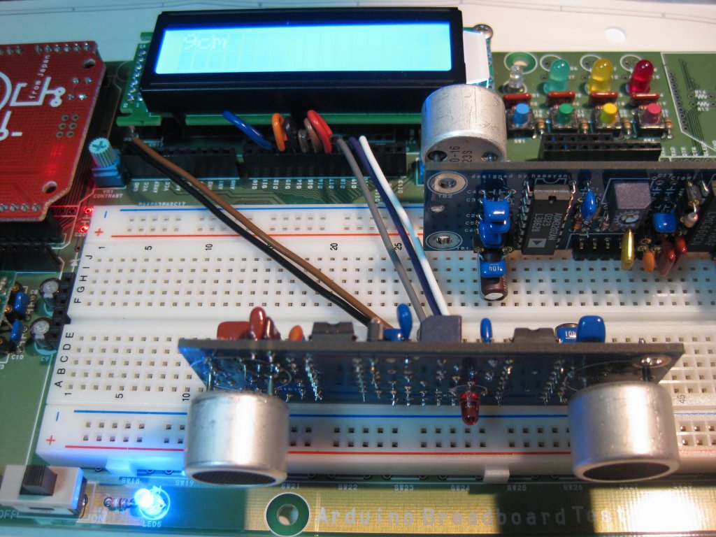
 MTM05の時にブレッドボードで組んでArduinoで動かして、それをPrototyping Labのトークセッションにて小林さんに紹介してもらった超音波距離計のモジュール基板です。
バンドパスフィルターの定数を決めるのに随分時間が掛かってしまった気もするけれど、わりと安定して動くようになりましたので、基板も量産してMTM06に持ち込む予定です。
基本的に基板のみの配付を予定しています。価格は実費のみの250円を予定しています。ただ部品セットの要望が大きければ検討いたします。
と言いますか、MTM06の会場で工具を用意しておきますので、その場で作ってみるみたいな事をしたいと思っています。
計測距離は8cm位から3m強測れます。
左右、上下の広がりですが、結構広い範囲を拾ってしまいますねこのセンサーは。なのでスポットで計測したい場合はホーンを付けた方が良さそうです。
データシートは以下のアドレスのT4016A1とR4016A1をご覧ください。
http://www.nicera.co.jp/pro/ut/ut-02.html
動かすマイコンはArduinoに限らずなんでも良いです。但し40KHz位の信号を出せる必要があります。

※秋月でニセラのT4016A1、R4016A1の扱いが無くなったと思いきや、今度は台湾メーカーでそっくりの品の扱いが始まったようです。
http://akizukidenshi.com/catalog/g/gI-00120/
購入して同様に使えるのか試してみます。
 MTM05の時にブレッドボードで組んでArduinoで動かして、それをPrototyping Labのトークセッションにて小林さんに紹介してもらった超音波距離計のモジュール基板です。
バンドパスフィルターの定数を決めるのに随分時間が掛かってしまった気もするけれど、わりと安定して動くようになりましたので、基板も量産してMTM06に持ち込む予定です。
基本的に基板のみの配付を予定しています。価格は実費のみの250円を予定しています。ただ部品セットの要望が大きければ検討いたします。
と言いますか、MTM06の会場で工具を用意しておきますので、その場で作ってみるみたいな事をしたいと思っています。
計測距離は8cm位から3m強測れます。
左右、上下の広がりですが、結構広い範囲を拾ってしまいますねこのセンサーは。なのでスポットで計測したい場合はホーンを付けた方が良さそうです。
データシートは以下のアドレスのT4016A1とR4016A1をご覧ください。
http://www.nicera.co.jp/pro/ut/ut-02.html
動かすマイコンはArduinoに限らずなんでも良いです。但し40KHz位の信号を出せる必要があります。
Prototyping Lab ―「作りながら考える」ためのArduino実践レシピ
- 作者: 小林 茂
- 出版社/メーカー: オライリージャパン
- 発売日: 2010/05/27
- メディア: 大型本
- 作者: Theodore Gray
- 出版社/メーカー: オライリージャパン
- 発売日: 2010/05/24
- メディア: 大型本
Maruduinoで時計を作る。Wireライブラリ対応版 [アプリケーション]
このボードはハムフェア(http://bit.ly/14qQxv)のマルツさんのブースで展示予定です。触ってネー。
 もっとも自分でなんとかした訳ではなく、某所から、ロジアナまで持ち出しての動作解析をしてもらった結果です。
ある意味Wireライブラリの使い方の見本としてもどうぞ。
※Wireライブラリの中で割込みを使っている関係上、別の割り込みハンドラの中から呼んだり、割り込み禁止にしている状態では、Wireライブラリを使う事ができない様です。お気を付け。
 もっとも自分でなんとかした訳ではなく、某所から、ロジアナまで持ち出しての動作解析をしてもらった結果です。
ある意味Wireライブラリの使い方の見本としてもどうぞ。
※Wireライブラリの中で割込みを使っている関係上、別の割り込みハンドラの中から呼んだり、割り込み禁止にしている状態では、Wireライブラリを使う事ができない様です。お気を付け。
/***********************************************************************/
/* LCD clock                                                           */
/* I2C bus control RTC()RTC8564 use                                    */
/*                                               designed by hamayan   */
/*                                               Copyright(C) hamayan  */
/***********************************************************************/
#include <string.h>
#include <LiquidCrystal.h>
#include <Wire.h>
#include <avr/io.h>

/*************************************************************************/
/* defines                                                               */
/*************************************************************************/
#define  DI13     13
#define  DI12     12
#define  DI11     11
#define  DI10     10
#define  DI9      9
#define  DI8      8
#define  DI7      7
#define  DI6      6
#define  DI5      5
#define  DI4      4
#define  DI3      3
#define  DI2      2
#define  DI1      1
#define  DI0      0
#define  AN0      14
#define  AN1      15
#define  AN2      16
#define  AN3      17
#define  AN4      18
#define  AN5      19

#define  SW1      AN3
#define  SW2      AN2
#define  SW3      AN1
#define  SW4      AN0

#define  RTC8564_CTRL1      0x00
#define  RTC8564_CTRL2      0x01
#define  RTC8564_SEC        0x02
#define  RTC8564_MIN        0x03
#define  RTC8564_HOUR       0x04
#define  RTC8564_DAY        0x05
#define  RTC8564_WEEK       0x06
#define  RTC8564_MONTH      0x07
#define  RTC8564_YEAR       0x08
#define  RTC8564_MIN_ALM    0x09
#define  RTC8564_HOUR_ALM   0x0A
#define  RTC8564_DAY_ALM    0x0B
#define  RTC8564_WEEK_ALM   0x0C
#define  RTC8564_CLK_FREQ   0x0D
#define  RTC8564_TIM_CTRL   0x0E
#define  RTC8564_TIMER      0x0F

#define  RTC_BASE_ADDR      (0xa2 >> 1)

/*************************************************************************/
/*  global parameter                                                     */
/*************************************************************************/
enum RTC8564Str {SECONDS,MINUTES,HOURS,DAYS,WEEKDAYS,MONTHS,YEARS};

/* 0123456789012345678 */
/* 2007/11/21 15:12:00 */
char date[ 20 ];  /**/
char alarm_set_time[] = "00:00";

unsigned long sectim;
unsigned long lasttim;
unsigned char switches[3];
boolean  clock_disp = false;

const char date_limit[][2] = /*offset = 2*/
{
  {'0','9'},  /*year 10*/
  {'0','9'},  /*year 1*/
  {'/','/'},  /**/
  {'0','1'},  /*month 10*/
  {'0','9'},  /*month 1*/
  {'/','/'},  /**/
  {'0','3'},  /*day 10*/
  {'0','9'},  /*day 1*/
};
const char time_limit[][2] = /*offset = 0*/
{
  {'0','2'},  /*hour 10*/
  {'0','9'},  /*hour 1*/
  {':',':'},  /**/
  {'0','5'},  /*monite 10*/
  {'0','9'},  /*monite 1*/
  {':',':'},  /**/
  {'0','5'},  /*second 10*/
  {'0','9'},  /*second 1*/
};

LiquidCrystal lcd(DI8, DI9, DI4, DI5, DI6, DI7);

/*************************************************************************/
/*  prototype                                                            */
/*************************************************************************/
static void date_print( const char *src, int x, int y );
static void time_print( const char *src, int x, int y );
static void ConvertFromRTC2DateTime( void );

int I2C_Write( int addr, unsigned char data );
int I2C_Read( int addr, unsigned char *data );

int InitRTC8564( int force );
unsigned char *DateStr2RTC8564Str( unsigned char *dest, const char *source );
char *RTC8564Str2DateStr( char *dest, const unsigned char source[] );
int I2CRTC8564_Write( unsigned char addr, char data );
int I2CRTC8564_Read( unsigned char addr, char *buff );
int I2CRTC8564_Blk_Read( unsigned char addr, char *buff, int size );
int RTC8564_CalenderSet( const char *date_time );

#define  CalenderRead(buf)  I2CRTC8564_Blk_Read(RTC8564_SEC, buf, 7)

/*************************************************************************/
/*  digital2 external int handler                                        */
/*************************************************************************/
static void di2_int_hdr( void )
{
  sectim++;
}

/*************************************************************************/
/*  time display update                                                  */
/*************************************************************************/
static void time_disp_update( void )
{
  ConvertFromRTC2DateTime();  /*update clock*/
  if( clock_disp == true )
  {
    date_print(date,0,0);
    time_print(date,2,1);
  }
}

/*************************************************************************/
/*  Switch down detection                                                */
/*************************************************************************/
static unsigned char detect_sw_down( unsigned char *sw )
{
  unsigned char temp = PINC & 0x0f;

  sw[0] = sw[1];
  sw[1] = sw[2];
  sw[2] = temp ^ 0x0f;

  return sw[0] & sw[1] & temp;
}

/*************************************************************************/
/*  RTC8564 data convert to date time strings.                           */
/*************************************************************************/
static void ConvertFromRTC2DateTime( void )
{
  char buf[10];

  CalenderRead( buf );
  RTC8564Str2DateStr( date, (const unsigned char *)buf );  /**/
}

/*************************************************************************/
/*  Date lcd print                                                       */
/*************************************************************************/
static void date_print( const char *src, int x, int y )
{
  char buf[16];

  memcpy( buf, src, 10 );
  buf[10] = '\0';
  lcd.setCursor(x,y);
  lcd.print( buf );
}

/*************************************************************************/
/*  Time lcd print                                                       */
/*************************************************************************/
static void time_print( const char *src, int x, int y )
{
  char buf[16];

  memcpy( buf, &src[11], 8 );
  buf[8] = '\0';
  lcd.setCursor(x,y);
  lcd.print( buf );
}

/*************************************************************************/
/*  Time adjust                                                          */
/*************************************************************************/
static void time_adjust_mode( void )
{
  int pos = 2;
  char copy_date[20];
  boolean loop = true;

  memcpy( copy_date, date, sizeof(copy_date) );
  lcd.clear();
  date_print(copy_date,0,0);
  lcd.setCursor(pos,1);
  lcd.print( '^' );

  while( loop )
  {
    delay( 100 );
    switch ( detect_sw_down( switches ) )
    {
      case 0b00000001:  /*confirm*/
        lcd.setCursor(pos,1);
        lcd.print( ' ' );
        if( ++pos == 10 )
        {
          loop = false;
          break;
        }
        if( pos == 4 || pos == 7 ) pos++;
        lcd.setCursor(pos,1);
        lcd.print( '^' );
        break;
      case 0b00000010:  /*down number*/
        if( --copy_date[pos] < date_limit[pos - 2][0] ) copy_date[pos] = date_limit[pos - 2][1];
        lcd.setCursor(pos,0);
        lcd.print( copy_date[pos] );
        break;
      case 0b00000100:  /*up number*/
        if( ++copy_date[pos] > date_limit[pos - 2][1] ) copy_date[pos] = date_limit[pos - 2][0];
        lcd.setCursor(pos,0);
        lcd.print( copy_date[pos] );
        break;
      case 0b00001000:  /*abort*/
        return;
      default:
        break;
    }
  }

  pos = 0;
  loop = true;
  lcd.clear();
  time_print(copy_date,0,0);
  lcd.setCursor(pos,1);
  lcd.print( '^' );

  while( loop )
  {
    delay( 100 );
    switch ( detect_sw_down( switches ) )
    {
      case 0b00000001:  /*confirm*/
        lcd.setCursor(pos,1);
        lcd.print( ' ' );
        if( ++pos == 8 )
        {
          loop = false;
          break;
        }
        if( pos == 2 || pos == 5 ) pos++;
        lcd.setCursor(pos,1);
        lcd.print( '^' );
        break;
      case 0b00000010:  /*down number*/
        if( --copy_date[pos + 11] < time_limit[pos][0] ) copy_date[pos + 11] = time_limit[pos][1];
        lcd.setCursor(pos,0);
        lcd.print( copy_date[pos + 11] );
        break;
      case 0b00000100:  /*up number*/
        if( ++copy_date[pos + 11] > time_limit[pos][1] ) copy_date[pos + 11] = time_limit[pos][0];
        lcd.setCursor(pos,0);
        lcd.print( copy_date[pos + 11] );
        break;
      case 0b00001000:  /*abort*/
        return;
      default:
        break;
    }
  }

  noInterrupts();  /*global interrupt disable*/
  EIMSK &= ~0x01;  /*int0 interrupt disable*/
  interrupts();    /*global interrupt enable*/
  memcpy( date, copy_date, sizeof(date) );
  RTC8564_CalenderSet( date );  /*update calender.*/
  EIMSK |= 0x01;   /*int0 interrupt enable*/
}

/*************************************************************************/
/*  Alarm set                                                            */
/*************************************************************************/
static void Alarm_set_mode( void )
{
  int pos = 0;
  unsigned char temp;
  boolean loop = true;

  lcd.clear();
  lcd.setCursor(0,0);
  lcd.print( alarm_set_time );
  lcd.setCursor(pos,1);
  lcd.print( '^' );

  while( loop )
  {
    delay( 100 );
    switch ( detect_sw_down( switches ) )
    {
      case 0b00000001:  /*confirm*/
        lcd.setCursor(pos,1);
        lcd.print( ' ' );
        if( ++pos == 5 )
        {
          loop = false;
          break;
        }
        if( pos == 2 ) pos++;
        lcd.setCursor(pos,1);
        lcd.print( '^' );
        break;
      case 0b00000010:  /*down number*/
        if( --alarm_set_time[pos] < time_limit[pos][0] ) alarm_set_time[pos] = time_limit[pos][1];
        lcd.setCursor(pos,0);
        lcd.print( alarm_set_time[pos] );
        break;
      case 0b00000100:  /*up number*/
        if( ++alarm_set_time[pos] > time_limit[pos][1] ) alarm_set_time[pos] = time_limit[pos][0];
        lcd.setCursor(pos,0);
        lcd.print( alarm_set_time[pos] );
        break;
      case 0b00001000:  /*abort*/
        return;
      default:
        break;
    }
  }

  temp = ((alarm_set_time[3] & 0x0f) << 4) + (alarm_set_time[4] & 0x0f);
  noInterrupts();  /*global interrupt disable*/
  EIMSK &= ~0x01;  /*int0 interrupt disable*/
  interrupts();    /*global interrupt enable*/
  I2CRTC8564_Write( RTC8564_MIN_ALM, temp );
  EIMSK |= 0x01;   /*int0 interrupt enable*/

  temp = ((alarm_set_time[0] & 0x0f) << 4) + (alarm_set_time[1] & 0x0f);
  noInterrupts();  /*global interrupt disable*/
  EIMSK &= ~0x01;  /*int0 interrupt disable*/
  interrupts();    /*global interrupt enable*/
  I2CRTC8564_Write( RTC8564_HOUR_ALM, temp );
  EIMSK |= 0x01;   /*int0 interrupt enable*/
}

/*************************************************************************/
/*  setup                                                                */
/*************************************************************************/
void setup()
{
  char buf[16];
  unsigned char temp;
//  static const char date_time[] = "2010/08/07 02:04:00";

  lcd.begin(16, 2);
  lcd.clear();
  lcd.println( "designed by hamayan." );

  Wire.begin();  /*set i2c master device*/
  TWSR &= 0xfc;  /*baud rate control. prescaler=x1*/
  TWBR = 72;     /*baud rate control. 100khz*/

  delay( 1000 );
  if( InitRTC8564( 0 ) < 0 )
  {
    lcd.clear();
    lcd.println( "rtc init error." );
    while(1) ;
  }

  I2CRTC8564_Read( RTC8564_MIN_ALM, (char *)&temp );
  if( !(temp & 0x80) )
  {
    alarm_set_time[3] = ((temp >> 4) & 0x07) + '0';
    alarm_set_time[4] = (temp & 0x0f) + '0';
    I2CRTC8564_Read( RTC8564_HOUR_ALM, (char *)&temp );
    alarm_set_time[0] = ((temp >> 4) & 0x03) + '0';
    alarm_set_time[1] = (temp & 0x0f) + '0';
  }

//  RTC8564_CalenderSet( date_time );  /*force setting calender.*/

  pinMode( SW1, INPUT );  /*set port at input mode*/
  pinMode( SW2, INPUT );  /*set port at input mode*/
  pinMode( SW3, INPUT );  /*set port at input mode*/
  pinMode( SW4, INPUT );  /*set port at input mode*/

  /*enable edge trigger interrupt*/
  attachInterrupt(0, di2_int_hdr, FALLING);
  DDRD &= ~0b00000100;  /*direction input*/
  PORTD |= 0b00000100;  /*enable pullup*/

  /*display alarm set time*/
  lcd.clear();
  lcd.setCursor(11,1);
  lcd.print( alarm_set_time );
  clock_disp = true;
  lasttim = millis() + 100;
}

/*************************************************************************/
/*  main loop                                                            */
/*************************************************************************/
void loop()
{
#define  ALARM_PERIOD  (60 * 5)
  unsigned char temp;
  static unsigned long oldsec;
  static int alarm_time;

  if( millis() > lasttim )
  {
    lasttim = millis() + 100;  /*next sample time update.*/
    switch ( detect_sw_down( switches ) )
    {
      case 0b00001010 :  /*time adjust mode*/
        clock_disp = false;
        time_adjust_mode();
        lcd.clear();
        lcd.setCursor(11,1);
        lcd.print( alarm_set_time );
        clock_disp = true;
        break;
      case 0b00001100 :  /*alarm set mode*/
        clock_disp = false;
        Alarm_set_mode();
        lcd.clear();
        lcd.setCursor(11,1);
        lcd.print( alarm_set_time );
        clock_disp = true;
        break;
      case 0b00001000 :  /*stop alarm*/
        alarm_time = 0;
        break;
      default :
        break;
    }
  }

  if( oldsec != sectim )
  {
    oldsec = sectim;
    time_disp_update();  /*clock display update*/

    if( date[18] == '0' &&
        date[17] == '0' &&
        alarm_set_time[4] == date[15] &&
        alarm_set_time[3] == date[14] &&
        alarm_set_time[1] == date[12] &&
        alarm_set_time[0] == date[11] )
      alarm_time = ALARM_PERIOD;  /*? minutes*/

    if( --alarm_time > 0 )
    {
      if( alarm_time % 3 ) tone( DI13, 1000, 800 );
    }
    else alarm_time = 0;
  }
}

/*************************************************************************/
/*  I2C Write function                                                   */
/*************************************************************************/
int I2C_Write( int addr, unsigned char data )
{
  Wire.beginTransmission( addr );
  Wire.send( data );
  return Wire.endTransmission();
}

/*************************************************************************/
/*  I2C Read function                                                    */
/*************************************************************************/
int I2C_Read( int addr, unsigned char *data )
{
  Wire.requestFrom( addr, 1 );
  while( Wire.available() == 0 ) ;
  *data = Wire.receive();
  return 0;
}

/*************************************************************************/
/* I2CRTC8564_Write                                                      */
/*************************************************************************/
int I2CRTC8564_Write( unsigned char addr, char data )
{
  Wire.beginTransmission( RTC_BASE_ADDR );
  Wire.send( addr );
  Wire.send( data );
  return Wire.endTransmission();
}

/*************************************************************************/
/* I2CRTC8564_Read                                                       */
/*************************************************************************/
int I2CRTC8564_Read( unsigned char addr, char *buff )
{
  Wire.beginTransmission( RTC_BASE_ADDR );
  Wire.send( addr );
  Wire.endTransmission();

  Wire.requestFrom( RTC_BASE_ADDR, 1 );
  while( Wire.available() == 0 ) ;
  *buff = Wire.receive();
  return 0;
}

/*************************************************************************/
/* I2CRTC8564_Blk_Read                                                   */
/*************************************************************************/
int I2CRTC8564_Blk_Read( unsigned char addr, char *buff, int size )
{
  Wire.beginTransmission( RTC_BASE_ADDR );
  Wire.send( addr );
  Wire.endTransmission();

  Wire.requestFrom( RTC_BASE_ADDR, size );
  while( Wire.available() < size ) ;
  for( ; size > 0; size-- )
  {
    *buff++ = Wire.receive();
  }
  return 0;
}

/*************************************************************************/
/* RTC-8564 initialize                                                   */
/*************************************************************************/
int InitRTC8564( int force )
{
  int i,ret;
  char temp,date_time[ 7 ],work[ 8 ];
  unsigned char rtc_adr;
  static const unsigned char RTC8564_Init_Code[] =
    {0x20, 0x11, 0x00,0x10,0x18,0x07,0x04,0x05, 0x10,0x80, 0x80,  0x80, 0x80,  0x00,0x81,63  };
   /*ctrl1,ctrl2,sec, min, hour,day, week,month,year,min_a,hour_a,day_a,week_a,freq,cont,timer*/

  /*RTC8564 confirmed VLbit*/
  if( I2CRTC8564_Read( RTC8564_SEC, &date_time[ SECONDS ] ) != 0 ) return (-1);

  if( date_time[ SECONDS ] & 0x80 || force )  /*VLbit was 1 then detected low voltage*/
  {
    for( rtc_adr = 0; rtc_adr < sizeof( RTC8564_Init_Code ); rtc_adr++ )
    {
      if( I2CRTC8564_Write( rtc_adr, RTC8564_Init_Code[ rtc_adr ] ) != 0 ) return (-1);
    }
    if( I2CRTC8564_Write( RTC8564_CTRL1, 0x00 ) != 0 ) return (-1);  /*timer start*/

    for( i = 0; i < 100; i++ )
    {
      if( I2CRTC8564_Read( RTC8564_YEAR, &date_time[ YEARS ] ) != 0 ) return (-1);  /*RTC is not there.*/

      if( date_time[ YEARS ] == RTC8564_Init_Code[ RTC8564_YEAR ] )  /**/
      {
        break;
      }
      else
      {
        for( rtc_adr = 0; rtc_adr <= sizeof( RTC8564_Init_Code ); rtc_adr++ )
        {
          if( I2CRTC8564_Write( rtc_adr, RTC8564_Init_Code[ rtc_adr ] ) != 0 ) return (-1);
        }
        if( I2CRTC8564_Write( RTC8564_CTRL1, 0x00 ) != 0 ) return (-1);
      }
    }
    if( i != 100 ) ret = 1;  /**/
    else ret = (-2);  /*initialize error*/
  }
  else ret = 0;

  if( ret > (-1) )
  {
    if( I2CRTC8564_Blk_Read( RTC8564_SEC, work, 7 ) != 0 ) return (-1);
    RTC8564Str2DateStr( date, (const unsigned char *)work );  /**/
  }

  return ret;
}

/*************************************************************************/
/*   0123456789012345678                                                 */
/*   2007/11/21 15:12:00                                                 */
/* DateStr2RTC8564Str( (unsigned char *)work, "2007/12/31 23:59:00" );   */
/* I2CRTC8564_Blk_Write( RTC8564_SEC, (const char *)work, 7 );           */
/*************************************************************************/
unsigned char *DateStr2RTC8564Str( unsigned char *dest, const char *source )
{
  dest[ 0 ] = ((source[ 17 ] & 0x07) << 4) | (source[ 18 ] & 0x0f);  /*second*/
  dest[ 1 ] = ((source[ 14 ] & 0x07) << 4) | (source[ 15 ] & 0x0f);  /*minute*/
  dest[ 2 ] = ((source[ 11 ] & 0x03) << 4) | (source[ 12 ] & 0x0f);  /*hour*/
  dest[ 3 ] = ((source[ 8 ] & 0x03) << 4) | (source[ 9 ] & 0x0f);  /*day*/
  dest[ 4 ] = 0;  /*week*/
  dest[ 5 ] = ((source[ 5 ] & 0x01) << 4) | (source[ 6 ] & 0x0f);  /*month*/
  dest[ 6 ] = ((source[ 2 ] & 0x0f) << 4) | (source[ 3 ] & 0x0f);  /*year*/

  return dest;
}

/*************************************************************************/
/*   0123456789012345678                                                 */
/*   2007/11/21 15:12:00                                                 */
/*************************************************************************/
char *RTC8564Str2DateStr( char *dest, const unsigned char source[] )
{
  dest[ 0 ] = '2';
  dest[ 1 ] = '0';
  dest[ 2 ] = (source[YEARS] >> 4) + '0';
  dest[ 3 ] = (source[YEARS] & 0x0f) + '0';
  dest[ 4 ] = '/';
  dest[ 5 ] = ((source[MONTHS] >> 4) & 0x01) + '0';
  dest[ 6 ] = (source[MONTHS] & 0x0f) + '0';
  dest[ 7 ] = '/';
  dest[ 8 ] = ((source[DAYS] >> 4) & 0x03) + '0';
  dest[ 9 ] = (source[DAYS] & 0x0f) + '0';
  dest[ 10 ] = ' ';
  dest[ 11 ] = ((source[HOURS] >> 4) & 0x03) + '0';
  dest[ 12 ] = (source[HOURS] & 0x0f) + '0';
  dest[ 13 ] = ':';
  dest[ 14 ] = ((source[MINUTES] >> 4) & 0x07) + '0';
  dest[ 15 ] = (source[MINUTES] & 0x0f) + '0';
  dest[ 16 ] = ':';
  dest[ 17 ] = ((source[SECONDS] >> 4) & 0x07) + '0';
  dest[ 18 ] = (source[SECONDS] & 0x0f) + '0';
  dest[ 19 ] = '\0';

  return dest;
}

/*************************************************************************/
/* RTC-8564 Calender Set                                                 */
/*************************************************************************/
int RTC8564_CalenderSet( const char *date_time )
{
  int i;
  unsigned char rtc_adr,work[ 8 ];

  DateStr2RTC8564Str( work, date_time );

  /*timer stop*/
  if( I2CRTC8564_Write( RTC8564_CTRL1, 0x20 ) != 0 ) return (-1);

  /*date and time write*/
  for( rtc_adr = RTC8564_SEC, i = 0; rtc_adr <= RTC8564_YEAR; rtc_adr++ )
  {
    if( I2CRTC8564_Write( rtc_adr, work[ i++ ] ) != 0 ) return (-1);
  }

  /*timer start*/
  if( I2CRTC8564_Write( RTC8564_CTRL1, 0x00 ) != 0 ) return (-1);

  return 0;
}

/***********************************************************************/
/*                                               designed by hamayan   */
/*                                               Copyright(C) hamayan  */
/***********************************************************************/
Prototyping Lab ―「作りながら考える」ためのArduino実践レシピ
- 作者: 小林 茂
- 出版社/メーカー: オライリージャパン
- 発売日: 2010/05/27
- メディア: 大型本
printfって便利だよね [アプリケーション]
 LiquidCrystalのprintライブラリは軽くて良いのですけれど、ちょっと不便なんですよね。
やっぱりprintfの簡単さは捨て難い物がある。特にデバッカーのサポートを受け難いArduinoでは、メッセージの出し方で随分開発効率が変わってくる。
と言う訳でツイッターでprintfの実現方法に触れられていましたので、LCD出力に適用してみました。
簡単なスケッチを下記に記載しておきます。
LCDとの接続はスケッチを参考としてください。と言うか、適宜自分の環境に合わせて変更してください。
※浮動小数点型には対応していないみたいです。
※生成可能な文字列の最大は、以下のスケッチなら127です。
#include <string.h>
#include <stdarg.h>
#include <LiquidCrystal.h>

LiquidCrystal lcd(12, 10, 5, 4, 3, 2);

void LCDPrintf( const char *fmt, ... )
{
  char tmp[128];
  va_list args;
  va_start( args, fmt );
  vsnprintf( tmp, sizeof(tmp), fmt, args );
  va_end( args );
  lcd.print( tmp );
}

void setup()
{
  lcd.begin(16, 2);
  lcd.clear();
  LCDPrintf( "designed by hamayan." );
}

void loop()
{
  static int i;

  lcd.setCursor(0,1);
  LCDPrintf( "count %+04d", i-- );
  delay( 100 );
}

- 作者: 柴田望洋
- 出版社/メーカー: ソフトバンククリエイティブ
- 発売日: 2004/08/28
- メディア: 単行本

- 作者: B.W. カーニハン
- 出版社/メーカー: 共立出版
- 発売日: 1989/06/15
- メディア: 単行本
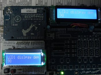
MaruduinoでDual Displayを実現する [アプリケーション]
実際のところとっても簡単に表示でき、情報量が2倍~です(笑)。
※タイプミスしているし(笑)
※ああ勿論、もっと沢山のLCDを増設できるんですよ。
 方法をご紹介するだけなので、サンプルアプリケーションも手抜きでexampleのHello,Worldを流用します。
まずその前に接続を行う必要があります。
今回使用するLCDは、基本パーツセットのLCDと、Prototyping Labの著者の小林様に譲っていただいたLCDシールド基板を組み立てた、この2つです。
LCDシールド基板の配線は既に基板上で行われていますので、敢えていじる所はありません。
基本パーツセットのLCDはご存知の様にユーザーが好きな接続を選べる様になっています。
以下の様に配線してください。
DI12(CN5)をRS(CN14)
DI10(CN5)をE(CN14)
DI5(CN5)をD4(CN14)
DI4(CN5)をD5(CN14)
DI3(CN5)をD6(CN14)
DI2(CN5)をD7(CN14)
です。つまりHello,Worldの基本的な接続の内、信号線Eへの配線が異なるのみです。
これは、個々のLCDを識別する為の信号線はEのみで済み、それ以外は共通化できるからです。
Eのみ個別の接続にし、新たにLCDインスタンスを生成すれば、LiquidCrystalライブラリで今まで通りに2つのLCDの制御が可能となります。
では具体的に改造したスケッチを以下に記載しておきます。すっごい簡単ですね。この辺がArduinoの良いところです。

※タイプミスしているし(笑)
※ああ勿論、もっと沢山のLCDを増設できるんですよ。
方法をご紹介するだけなので、サンプルアプリケーションも手抜きでexampleのHello,Worldを流用します。まずその前に接続を行う必要があります。
今回使用するLCDは、基本パーツセットのLCDと、Prototyping Labの著者の小林様に譲っていただいたLCDシールド基板を組み立てた、この2つです。
LCDシールド基板の配線は既に基板上で行われていますので、敢えていじる所はありません。
基本パーツセットのLCDはご存知の様にユーザーが好きな接続を選べる様になっています。
以下の様に配線してください。
DI12(CN5)をRS(CN14)
DI10(CN5)をE(CN14)
DI5(CN5)をD4(CN14)
DI4(CN5)をD5(CN14)
DI3(CN5)をD6(CN14)
DI2(CN5)をD7(CN14)
です。つまりHello,Worldの基本的な接続の内、信号線Eへの配線が異なるのみです。
これは、個々のLCDを識別する為の信号線はEのみで済み、それ以外は共通化できるからです。
Eのみ個別の接続にし、新たにLCDインスタンスを生成すれば、LiquidCrystalライブラリで今まで通りに2つのLCDの制御が可能となります。
では具体的に改造したスケッチを以下に記載しておきます。すっごい簡単ですね。この辺がArduinoの良いところです。
#include <LiquidCrystal.h>

// initialize the library with the numbers of the interface pins
LiquidCrystal lcd(12, 11, 5, 4, 3, 2);
LiquidCrystal lcd2(12, 10, 5, 4, 3, 2);

void setup() {
  // set up the LCD's number of rows and columns:
  lcd.begin(16, 2);
  lcd2.begin(16, 2);
  // Print a message to the LCD.
  lcd.print("LCD1 display demo.");
  lcd2.print("LCD2 display demo.");
}

void loop() {
  // set the cursor to column 0, line 1
  // (note: line 1 is the second row, since counting begins with 0):
  lcd.setCursor(0, 1);
  lcd2.setCursor(0, 1);
  // print the number of seconds since reset:
  lcd.print(millis()/1000);
  lcd2.print(millis()/1000);
}
Prototyping Lab ―「作りながら考える」ためのArduino実践レシピ
- 作者: 小林 茂
- 出版社/メーカー: オライリージャパン
- 発売日: 2010/05/27
- メディア: 大型本
武蔵野電波のブレッドボーダーズ―誰でも作れる!遊べる電子工作
- 作者: スタパ齋藤
- 出版社/メーカー: オーム社
- 発売日: 2009/11
- メディア: 単行本


