Maruduinoで時計を作る。リアルタイムクロック(RTC MRX-8564)の利用。 [アプリケーション]
組み立て編はこちらです。
http://maruduino.blog.so-net.ne.jp/2010-08-07
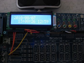 組み立てが完了したので、簡単な?スケッチを記述してみました。ご参考になれば幸いです。
Wireライブラリを使って通信してみたのですが、あまり安定しない、読み出しがおかしい?などがあったので、ソフトウエアでI2C通信を実現しています。
Arduinoは勿論マスターモードとしています。
操作方法を書いておきます。
時刻設定モード:
SW1とSW3の同時押しで時刻設定モードに入ります。
LCDの上段には変更する日付または時刻が表示され、下段には変更位置を示すポインターが表示されています。
SW2で数字を増やし、SW3で数字を減らしますが、上限、下限まで達すると循環します。
数字が確定したらSW4で次の項目に移動します。最後の項目である秒の変更が完了してSW4を押すと、その時点で時刻設定が確定します。
※SW1を押すと入力を取りやめ、通常の時刻表示モードに戻ります。
日付や時刻の整合性はあまりチェックしていませんので、注意してください。
アラーム設定モード:
SW1とSW2の同時押しでアラーム設定モードに入ります。
時刻設定モードと同様上段には時刻、下段にはポインターが表示されます。
その他操作も時刻設定モードと同じです。
時刻の整合性はあまりチェックしていませんので、注意してください。
※アラームを鳴らしたくない時は24:00に設定してください。
アラーム鳴動解除:
アラーム鳴動中にSW1を押す事で鳴動を解除できます。
バッテリーバックアップがされているので、電源を落としても時刻の更新やアラーム時刻の保持は行われています。
こうやってプロトタイピングして、もっとコンパクトであったり、電池で駆動できるものを作って日々の生活に役立てるとか良いですよね。
実際、Arduinoではありませんが、別のOne Chipマイコンで作った自作の目覚まし時計に日々起こされていますヨ。
以下にスケッチを記述しておきます。
※関数time_adjust_mode、Alarm_set_modeにアトミックな処理を追加 2010/08/07 18:35
/***********************************************************************/
/* LCD clock */
/* I2C bus control RTC()RTC8564 use */
/* designed by hamayan */
/* Copyright(C) hamayan */
/***********************************************************************/
#define _SOFT_I2C_
#if defined( _SOFT_I2C_ )
#else
#include <Wire.h>
#endif
#include <string.h>
#include <LiquidCrystal.h>
#include <avr/io.h>
/*************************************************************************/
/* defines */
/*************************************************************************/
#define DI13 13
#define DI12 12
#define DI11 11
#define DI10 10
#define DI9 9
#define DI8 8
#define DI7 7
#define DI6 6
#define DI5 5
#define DI4 4
#define DI3 3
#define DI2 2
#define DI1 1
#define DI0 0
#define AN0 14
#define AN1 15
#define AN2 16
#define AN3 17
#define AN4 18
#define AN5 19
#define SW1 AN3
#define SW2 AN2
#define SW3 AN1
#define SW4 AN0
#define SCL_BIT 0b00100000 /*PC5=SCL*/
#define SDA_BIT 0b00010000 /*PC4=SDA*/
#define SCL_IS_HIGH PORTC |= SCL_BIT /*about 120ns swittching*/
#define SCL_IS_LOW PORTC &= ~SCL_BIT /*about 120ns swittching*/
#define SDA_IS_HIGH PORTC |= SDA_BIT /*about 120ns swittching*/
#define SDA_IS_LOW PORTC &= ~SDA_BIT /*about 120ns swittching*/
#define SDA_OUTPUT DDRC |= SDA_BIT
#define SDA_INPUT DDRC &= ~SDA_BIT
#define SCL_OUTPUT DDRC |= SCL_BIT
#define ACK 0 /*ACK Bit*/
#define NACK 1 /*NACK Bit*/
#define RTC8564_CTRL1 0x00
#define RTC8564_CTRL2 0x01
#define RTC8564_SEC 0x02
#define RTC8564_MIN 0x03
#define RTC8564_HOUR 0x04
#define RTC8564_DAY 0x05
#define RTC8564_WEEK 0x06
#define RTC8564_MONTH 0x07
#define RTC8564_YEAR 0x08
#define RTC8564_MIN_ALM 0x09
#define RTC8564_HOUR_ALM 0x0A
#define RTC8564_DAY_ALM 0x0B
#define RTC8564_WEEK_ALM 0x0C
#define RTC8564_CLK_FREQ 0x0D
#define RTC8564_TIM_CTRL 0x0E
#define RTC8564_TIMER 0x0F
#if defined( _SOFT_I2C_ )
#define RTC_BASE_ADDR (0xa2)
#else
#define RTC_BASE_ADDR (0xa2 >> 1)
#endif
/*************************************************************************/
/* global parameter */
/*************************************************************************/
enum RTC8564Str {SECONDS,MINUTES,HOURS,DAYS,WEEKDAYS,MONTHS,YEARS};
/* 0123456789012345678 */
/* 2007/11/21 15:12:00 */
char date[ 20 ]; /**/
char alarm_set_time[] = "00:00";
unsigned long sectim;
unsigned long lasttim;
unsigned char switches[3];
boolean clock_disp = false;
const char date_limit[][2] = /*offset = 2*/
{
{'0','9'}, /*year 10*/
{'0','9'}, /*year 1*/
{'/','/'}, /**/
{'0','1'}, /*month 10*/
{'0','9'}, /*month 1*/
{'/','/'}, /**/
{'0','3'}, /*day 10*/
{'0','9'}, /*day 1*/
};
const char time_limit[][2] = /*offset = 0*/
{
{'0','2'}, /*hour 10*/
{'0','9'}, /*hour 1*/
{':',':'}, /**/
{'0','5'}, /*monite 10*/
{'0','9'}, /*monite 1*/
{':',':'}, /**/
{'0','5'}, /*second 10*/
{'0','9'}, /*second 1*/
};
LiquidCrystal lcd(DI8, DI9, DI4, DI5, DI6, DI7);
/*************************************************************************/
/* prototype */
/*************************************************************************/
static void clk100( void );
static void I2C_Terminate( void );
static void StartCondition( void );
static void StopCondition( void );
static int RcvAck( void );
static void ResAck( int ack );
static void BitWrite( int data );
static int BitRead( void );
static int ByteWrite( int data );
static int ByteRead( int ack );
static void date_print( const char *src, int x, int y );
static void time_print( const char *src, int x, int y );
static void ConvertFromRTC2DateTime( void );
void I2C_Init( void );
int I2C_Block_Write( int addr, const char *data, int size );
int I2C_Block_Read( int addr, char *data, int size );
int I2C_Write( int addr, unsigned char data );
int I2C_Read( int addr, unsigned char *data );
int InitRTC8564( int force );
unsigned char *DateStr2RTC8564Str( unsigned char *dest, const char *source );
char *RTC8564Str2DateStr( char *dest, const unsigned char source[] );
int I2CRTC8564_Write( unsigned char addr, char data );
int I2CRTC8564_Read( unsigned char addr, char *buff );
int I2CRTC8564_Blk_Read( unsigned char addr, char *buff, int size );
int I2CRTC8564_Blk_Write( unsigned char addr, const char *data, int size );
int RTC8564_CalenderSet( const char *date_time );
#define CalenderRead(buf) I2CRTC8564_Blk_Read(RTC8564_SEC, buf, 7)
/*************************************************************************/
/* digital2 external int handler */
/*************************************************************************/
static void di2_int_hdr( void )
{
sectim++;
ConvertFromRTC2DateTime(); /*update clock*/
if( clock_disp == true )
{
date_print(date,0,0);
time_print(date,2,1);
}
}
/*************************************************************************/
/* Switch down detection */
/*************************************************************************/
static unsigned char detect_sw_down( unsigned char *sw )
{
unsigned char temp = PINC & 0x0f;
sw[0] = sw[1];
sw[1] = sw[2];
sw[2] = temp ^ 0x0f;
return sw[0] & sw[1] & temp;
}
/*************************************************************************/
/* RTC8564 data convert to date time strings. */
/*************************************************************************/
static void ConvertFromRTC2DateTime( void )
{
char buf[10];
CalenderRead( buf );
RTC8564Str2DateStr( date, (const unsigned char *)buf ); /**/
}
/*************************************************************************/
/* Date lcd print */
/*************************************************************************/
static void date_print( const char *src, int x, int y )
{
char buf[16];
memcpy( buf, src, 10 );
buf[10] = '\0';
lcd.setCursor(x,y);
lcd.print( buf );
}
/*************************************************************************/
/* Time lcd print */
/*************************************************************************/
static void time_print( const char *src, int x, int y )
{
char buf[16];
memcpy( buf, &src[11], 8 );
buf[8] = '\0';
lcd.setCursor(x,y);
lcd.print( buf );
}
/*************************************************************************/
/* Time adjust */
/*************************************************************************/
static void time_adjust_mode( void )
{
int pos = 2;
char copy_date[20];
boolean loop = true;
memcpy( copy_date, date, sizeof(copy_date) );
lcd.clear();
date_print(copy_date,0,0);
lcd.setCursor(pos,1);
lcd.print( '^' );
while( loop )
{
delay( 100 );
switch ( detect_sw_down( switches ) )
{
case 0b00000001: /*confirm*/
lcd.setCursor(pos,1);
lcd.print( ' ' );
if( ++pos == 10 )
{
loop = false;
break;
}
if( pos == 4 || pos == 7 ) pos++;
lcd.setCursor(pos,1);
lcd.print( '^' );
break;
case 0b00000010: /*down number*/
if( --copy_date[pos] < date_limit[pos - 2][0] ) copy_date[pos] = date_limit[pos - 2][1];
lcd.setCursor(pos,0);
lcd.print( copy_date[pos] );
break;
case 0b00000100: /*up number*/
if( ++copy_date[pos] > date_limit[pos - 2][1] ) copy_date[pos] = date_limit[pos - 2][0];
lcd.setCursor(pos,0);
lcd.print( copy_date[pos] );
break;
case 0b00001000: /*abort*/
return;
default:
break;
}
}
pos = 0;
loop = true;
lcd.clear();
time_print(copy_date,0,0);
lcd.setCursor(pos,1);
lcd.print( '^' );
while( loop )
{
delay( 100 );
switch ( detect_sw_down( switches ) )
{
case 0b00000001: /*confirm*/
lcd.setCursor(pos,1);
lcd.print( ' ' );
if( ++pos == 8 )
{
loop = false;
break;
}
if( pos == 2 || pos == 5 ) pos++;
lcd.setCursor(pos,1);
lcd.print( '^' );
break;
case 0b00000010: /*down number*/
if( --copy_date[pos + 11] < time_limit[pos][0] ) copy_date[pos + 11] = time_limit[pos][1];
lcd.setCursor(pos,0);
lcd.print( copy_date[pos + 11] );
break;
case 0b00000100: /*up number*/
if( ++copy_date[pos + 11] > time_limit[pos][1] ) copy_date[pos + 11] = time_limit[pos][0];
lcd.setCursor(pos,0);
lcd.print( copy_date[pos + 11] );
break;
case 0b00001000: /*abort*/
return;
default:
break;
}
}
noInterrupts(); /*global interrupt disable*/
EIMSK &= ~0x01; /*int0 interrupt disable*/
interrupts(); /*global interrupt enable*/
memcpy( date, copy_date, sizeof(date) );
RTC8564_CalenderSet( date ); /*update calender.*/
EIMSK |= 0x01; /*int0 interrupt enable*/
}
/*************************************************************************/
/* Alarm set */
/*************************************************************************/
static void Alarm_set_mode( void )
{
int pos = 0;
unsigned char temp;
boolean loop = true;
lcd.clear();
lcd.setCursor(0,0);
lcd.print( alarm_set_time );
lcd.setCursor(pos,1);
lcd.print( '^' );
while( loop )
{
delay( 100 );
switch ( detect_sw_down( switches ) )
{
case 0b00000001: /*confirm*/
lcd.setCursor(pos,1);
lcd.print( ' ' );
if( ++pos == 5 )
{
loop = false;
break;
}
if( pos == 2 ) pos++;
lcd.setCursor(pos,1);
lcd.print( '^' );
break;
case 0b00000010: /*down number*/
if( --alarm_set_time[pos] < time_limit[pos][0] ) alarm_set_time[pos] = time_limit[pos][1];
lcd.setCursor(pos,0);
lcd.print( alarm_set_time[pos] );
break;
case 0b00000100: /*up number*/
if( ++alarm_set_time[pos] > time_limit[pos][1] ) alarm_set_time[pos] = time_limit[pos][0];
lcd.setCursor(pos,0);
lcd.print( alarm_set_time[pos] );
break;
case 0b00001000: /*abort*/
return;
default:
break;
}
}
temp = ((alarm_set_time[3] & 0x0f) << 4) + (alarm_set_time[4] & 0x0f);
noInterrupts(); /*global interrupt disable*/
EIMSK &= ~0x01; /*int0 interrupt disable*/
interrupts(); /*global interrupt enable*/
I2CRTC8564_Write( RTC8564_MIN_ALM, temp );
EIMSK |= 0x01; /*int0 interrupt enable*/
temp = ((alarm_set_time[0] & 0x0f) << 4) + (alarm_set_time[1] & 0x0f);
noInterrupts(); /*global interrupt disable*/
EIMSK &= ~0x01; /*int0 interrupt disable*/
interrupts(); /*global interrupt enable*/
I2CRTC8564_Write( RTC8564_HOUR_ALM, temp );
EIMSK |= 0x01; /*int0 interrupt enable*/
}
/*************************************************************************/
/* setup */
/*************************************************************************/
void setup()
{
char buf[16];
unsigned char temp;
// static const char date_time[] = "2010/08/07 02:04:00";
lcd.begin(16, 2);
lcd.clear();
lcd.println( "designed by hamayan." );
#if defined( _SOFT_I2C_ )
I2C_Init();
#else /*_SOFT_I2C_*/
Wire.begin(); /*set i2c master device*/
TWSR &= 0xfc; /*baud rate control. prescaler=x1*/
TWBR = 72; /*baud rate control. 100khz*/
#endif /*_SOFT_I2C_*/
delay( 1000 );
if( InitRTC8564( 0 ) < 0 )
{
lcd.clear();
lcd.println( "rtc init error." );
while(1) ;
}
I2CRTC8564_Read( RTC8564_MIN_ALM, (char *)&temp );
if( !(temp & 0x80) )
{
alarm_set_time[3] = ((temp >> 4) & 0x07) + '0';
alarm_set_time[4] = (temp & 0x0f) + '0';
I2CRTC8564_Read( RTC8564_HOUR_ALM, (char *)&temp );
alarm_set_time[0] = ((temp >> 4) & 0x03) + '0';
alarm_set_time[1] = (temp & 0x0f) + '0';
}
// RTC8564_CalenderSet( date_time ); /*force setting calender.*/
pinMode( SW1, INPUT ); /*set port at input mode*/
pinMode( SW2, INPUT ); /*set port at input mode*/
pinMode( SW3, INPUT ); /*set port at input mode*/
pinMode( SW4, INPUT ); /*set port at input mode*/
/*enable edge trigger interrupt*/
attachInterrupt(0, di2_int_hdr, FALLING);
DDRD &= ~0b00000100; /*direction input*/
PORTD |= 0b00000100; /*enable pullup*/
/*display alarm set time*/
lcd.clear();
lcd.setCursor(11,1);
lcd.print( alarm_set_time );
clock_disp = true;
lasttim = millis() + 100;
}
/*************************************************************************/
/* main loop */
/*************************************************************************/
void loop()
{
#define ALARM_PERIOD (60 * 5)
unsigned char temp;
static unsigned long oldsec;
static int alarm_time;
if( millis() > lasttim )
{
lasttim = millis() + 100; /*next sample time update.*/
switch ( detect_sw_down( switches ) )
{
case 0b00001010 : /*time adjust mode*/
clock_disp = false;
time_adjust_mode();
lcd.clear();
lcd.setCursor(11,1);
lcd.print( alarm_set_time );
clock_disp = true;
break;
case 0b00001100 : /*alarm set mode*/
clock_disp = false;
Alarm_set_mode();
lcd.clear();
lcd.setCursor(11,1);
lcd.print( alarm_set_time );
clock_disp = true;
break;
case 0b00001000 : /*stop alarm*/
alarm_time = 0;
break;
default :
break;
}
}
if( oldsec != sectim )
{
oldsec = sectim;
if( date[18] == '0' &&
date[17] == '0' &&
alarm_set_time[4] == date[15] &&
alarm_set_time[3] == date[14] &&
alarm_set_time[1] == date[12] &&
alarm_set_time[0] == date[11] )
alarm_time = ALARM_PERIOD; /*? minutes*/
if( --alarm_time > 0 )
{
if( alarm_time % 3 ) tone( DI13, 1000, 800 );
}
else alarm_time = 0;
}
}
/*************************************************************************/
/* wait functions */
/*************************************************************************/
#define wait1u() delayMicroseconds(1)
#define wait5u() delayMicroseconds(5)
/*************************************************************************/
/* 100 clocks function */
/*************************************************************************/
static void clk100( void )
{
int i;
/*i2c lock release*/
for( i = 0; i < 100; i++ )
{
SCL_IS_LOW;
wait1u();
SCL_IS_HIGH;
wait1u();
}
}
/*************************************************************************/
/* initialize function */
/*************************************************************************/
void I2C_Init( void )
{
int i;
PORTC |= SDA_BIT | SCL_BIT;
DDRC |= SDA_BIT | SCL_BIT; /*pc4=sda,pc5=scl*/
for( i = 0; i < 100; i++ )
{
SCL_IS_LOW;
wait1u();
SCL_IS_HIGH;
wait1u();
}
SDA_IS_LOW;
StopCondition();
wait5u();
}
/*************************************************************************/
/* I2C Terminate function */
/*************************************************************************/
static void I2C_Terminate( void )
{
SCL_OUTPUT;
SDA_OUTPUT;
SCL_IS_HIGH; /*about 120ns*/
SCL_IS_HIGH; /*about 120ns*/
SCL_IS_HIGH; /*about 120ns*/
SCL_IS_HIGH; /*about 120ns*/
SCL_IS_HIGH; /*about 120ns*/
SDA_IS_HIGH;
}
/*************************************************************************/
/* start condition */
/*************************************************************************/
static void StartCondition( void )
{
I2C_Terminate();
wait1u();
SDA_IS_LOW; /*about 120ns*/
SDA_IS_LOW; /*about 120ns*/
SDA_IS_LOW; /*about 120ns*/
SDA_IS_LOW; /*about 120ns*/
SDA_IS_LOW; /*about 120ns*/
SCL_IS_LOW;
}
/*************************************************************************/
/* stop condition */
/*************************************************************************/
static void StopCondition( void )
{
SCL_OUTPUT;
SDA_OUTPUT;
SCL_IS_HIGH; /*about 120ns*/
SCL_IS_HIGH; /*about 120ns*/
SCL_IS_HIGH; /*about 120ns*/
SCL_IS_HIGH; /*about 120ns*/
SCL_IS_HIGH; /*about 120ns*/
SDA_IS_HIGH;
}
/*************************************************************************/
/* ACK confirm function */
/*************************************************************************/
static int RcvAck( void )
{
int ret;
SCL_IS_LOW; /*about 120ns*/
SDA_INPUT;
wait1u();
SCL_IS_HIGH;
ret = (PINC & SDA_BIT) ? 1 : 0;
SCL_IS_HIGH; /*about 120ns*/
SCL_IS_HIGH; /*about 120ns*/
SDA_OUTPUT;
SCL_IS_LOW;
return ret;
}
/*************************************************************************/
/* ACK responce function */
/*************************************************************************/
static void ResAck( int ack )
{
SCL_IS_LOW; /*about 120ns*/
if(ack) SDA_IS_HIGH;
else SDA_IS_LOW;
wait1u();
SCL_IS_HIGH; /*about 120ns*/
SCL_IS_HIGH; /*about 120ns*/
SCL_IS_HIGH; /*about 120ns*/
SCL_IS_HIGH; /*about 120ns*/
SCL_IS_HIGH; /*about 120ns*/
SCL_IS_LOW;
SDA_IS_LOW;
}
/*************************************************************************/
/* Bit Write function */
/*************************************************************************/
static void BitWrite( int data )
{
SCL_IS_LOW; /*about 120ns*/
if(data) SDA_IS_HIGH;
else SDA_IS_LOW;
wait1u();
SCL_IS_HIGH; /*about 120ns*/
SCL_IS_HIGH; /*about 120ns*/
SCL_IS_HIGH; /*about 120ns*/
SCL_IS_HIGH; /*about 120ns*/
SCL_IS_HIGH; /*about 120ns*/
SCL_IS_LOW;
SDA_IS_LOW;
}
/*************************************************************************/
/* Bit Read function */
/*************************************************************************/
static int BitRead( void )
{
int ret;
SCL_IS_LOW; /*about 120ns*/
wait1u();
SCL_IS_HIGH;
ret = (PINC & SDA_BIT) ? 1 : 0;
SCL_IS_HIGH; /*about 120ns*/
SCL_IS_HIGH; /*about 120ns*/
SCL_IS_LOW;
return ret;
}
/*************************************************************************/
/* Byte Write function */
/*************************************************************************/
static int ByteWrite( int data )
{
BitWrite( data & 0x80 );
BitWrite( data & 0x40 );
BitWrite( data & 0x20 );
BitWrite( data & 0x10 );
BitWrite( data & 0x08 );
BitWrite( data & 0x04 );
BitWrite( data & 0x02 );
BitWrite( data & 0x01 );
// SDA_IS_LOW;
return ( RcvAck() == 0 ) ? 0 : (-1);
}
/*************************************************************************/
/* Byte Read function */
/*************************************************************************/
static int ByteRead( int ack )
{
int data = 0;
SDA_INPUT;
data |= ( BitRead() ) ? 0x80 : 0x00;
data |= ( BitRead() ) ? 0x40 : 0x00;
data |= ( BitRead() ) ? 0x20 : 0x00;
data |= ( BitRead() ) ? 0x10 : 0x00;
data |= ( BitRead() ) ? 0x08 : 0x00;
data |= ( BitRead() ) ? 0x04 : 0x00;
data |= ( BitRead() ) ? 0x02 : 0x00;
data |= ( BitRead() ) ? 0x01 : 0x00;
SDA_OUTPUT;
ResAck( ack );
return data;
}
/*************************************************************************/
/* I2C Block Write function */
/*************************************************************************/
int I2C_Block_Write( int addr, const char *data, int size )
{
StartCondition();
if( ByteWrite( addr ) == (-1) )
{
I2C_Terminate();
return (-1);
}
for( ; size > 0; size-- )
{
if( ByteWrite( *data++ ) == (-1) )
{
I2C_Terminate();
return (-1);
}
}
StopCondition();
return 0;
}
/*************************************************************************/
/* I2C Block Read function */
/*************************************************************************/
int I2C_Block_Read( int addr, char *data, int size )
{
StartCondition();
if( ByteWrite( addr | 0x01 ) == (-1) )
{
I2C_Terminate();
return (-1);
}
for( ; size > 0; size-- ) *data++ = ByteRead( (size == 1) ? 1 : 0 );
StopCondition();
return 0;
}
/*************************************************************************/
/* I2C Write function */
/*************************************************************************/
int I2C_Write( int addr, unsigned char data )
{
#if defined( _SOFT_I2C_ )
StartCondition();
if( ByteWrite( addr ) == (-1) )
{
I2C_Terminate();
clk100();
return (-1);
}
if( ByteWrite( data ) == (-1) )
{
I2C_Terminate();
clk100();
return (-1);
}
StopCondition();
return 0;
#else /*_SOFT_I2C_*/
Wire.beginTransmission( addr );
Wire.send( data );
return Wire.endTransmission();
#endif /*_SOFT_I2C_*/
}
/*************************************************************************/
/* I2C Read function */
/*************************************************************************/
int I2C_Read( int addr, unsigned char *data )
{
#if defined( _SOFT_I2C_ )
StartCondition();
if( ByteWrite( addr | 0x01 ) == (-1) )
{
I2C_Terminate();
clk100();
return (-1);
}
*data = ByteRead( 1 );
StopCondition();
return 0;
#else /*_SOFT_I2C_*/
Wire.requestFrom( addr, 1 );
while( Wire.available() == 0 ) ;
*data = Wire.receive();
return Wire.endTransmission();
#endif /*_SOFT_I2C_*/
}
/*************************************************************************/
/* I2CRTC8564_Write */
/*************************************************************************/
int I2CRTC8564_Write( unsigned char addr, char data )
{
#if defined( _SOFT_I2C_ )
StartCondition();
if( ByteWrite( RTC_BASE_ADDR ) == (-1) )
{
I2C_Terminate();
clk100();
return (-1);
}
if( ByteWrite( addr ) == (-1) )
{
I2C_Terminate();
clk100();
return (-1);
}
if( ByteWrite( data ) == (-1) )
{
I2C_Terminate();
clk100();
return (-1);
}
StopCondition();
return 0;
#else /*_SOFT_I2C_*/
Wire.beginTransmission( RTC_BASE_ADDR );
Wire.send( addr );
Wire.send( data );
return Wire.endTransmission();
#endif /*_SOFT_I2C_*/
}
/*************************************************************************/
/* I2CRTC8564_Read */
/*************************************************************************/
int I2CRTC8564_Read( unsigned char addr, char *buff )
{
#if defined( _SOFT_I2C_ )
StartCondition();
if( ByteWrite( RTC_BASE_ADDR ) == (-1) )
{
I2C_Terminate();
clk100();
return (-1);
}
if( ByteWrite( addr ) == (-1) )
{
I2C_Terminate();
clk100();
return (-1);
}
SDA_IS_HIGH;
SCL_IS_HIGH; /*about 120ns*/
SCL_IS_HIGH; /*about 120ns*/
SCL_IS_HIGH; /*about 120ns*/
SCL_IS_HIGH; /*about 120ns*/
SCL_IS_HIGH; /*about 120ns*/
SDA_IS_LOW; /*about 120ns*/
SDA_IS_LOW; /*about 120ns*/
SDA_IS_LOW; /*about 120ns*/
SDA_IS_LOW; /*about 120ns*/
SDA_IS_LOW; /*about 120ns*/
if( ByteWrite( RTC_BASE_ADDR | 0x01 ) == (-1) )
{
I2C_Terminate();
clk100();
return (-1);
}
*buff = ByteRead( 1 );
StopCondition();
return 0;
#else /*_SOFT_I2C_*/
Wire.beginTransmission( RTC_BASE_ADDR );
Wire.send( addr );
Wire.requestFrom( RTC_BASE_ADDR, 1 );
while( Wire.available() == 0 ) ;
*buff = Wire.receive();
return Wire.endTransmission();
#endif /*_SOFT_I2C_*/
}
/*************************************************************************/
/* I2CRTC8564_Blk_Read */
/*************************************************************************/
int I2CRTC8564_Blk_Read( unsigned char addr, char *buff, int size )
{
#if defined( _SOFT_I2C_ )
char *ptr = buff;
char *limit = &buff[ size - 1 ];
StartCondition();
if( ByteWrite( RTC_BASE_ADDR ) == (-1) )
{
I2C_Terminate();
clk100();
return (-1);
}
if( ByteWrite( addr ) == (-1) )
{
I2C_Terminate();
clk100();
return (-1);
}
SDA_IS_HIGH;
SCL_IS_HIGH; /*about 120ns*/
SCL_IS_HIGH; /*about 120ns*/
SCL_IS_HIGH; /*about 120ns*/
SCL_IS_HIGH; /*about 120ns*/
SCL_IS_HIGH; /*about 120ns*/
SDA_IS_LOW; /*about 120ns*/
SDA_IS_LOW; /*about 120ns*/
SDA_IS_LOW; /*about 120ns*/
SDA_IS_LOW; /*about 120ns*/
SDA_IS_LOW; /*about 120ns*/
if( ByteWrite( RTC_BASE_ADDR | 0x01 ) == (-1) )
{
I2C_Terminate();
clk100();
return (-1);
}
while( ptr < limit )
{
*ptr++ = ByteRead( 0 );
}
*ptr = ByteRead( 1 );
StopCondition();
return 0;
#else /*_SOFT_I2C_*/
Wire.beginTransmission( RTC_BASE_ADDR );
Wire.send( addr );
Wire.requestFrom( RTC_BASE_ADDR, size );
while( Wire.available() < size ) ;
for( ; size > 0; size-- )
{
*buff++ = Wire.receive();
}
return Wire.endTransmission();
#endif /*_SOFT_I2C_*/
}
/*************************************************************************/
/* I2CRTC8564_Blk_Write */
/*************************************************************************/
int I2CRTC8564_Blk_Write( unsigned char addr, const char *data, int size )
{
#if defined( _SOFT_I2C_ )
const char *ptr = data;
const char *limit = &data[ size ];
StartCondition();
if( ByteWrite( RTC_BASE_ADDR ) == (-1) )
{
I2C_Terminate();
clk100();
return (-1);
}
if( ByteWrite( addr ) == (-1) )
{
I2C_Terminate();
clk100();
return (-1);
}
while( ptr < limit )
{
if( ByteWrite( *ptr++ ) == (-1) )
{
I2C_Terminate();
clk100();
return (-1);
}
}
StopCondition();
return 0;
#endif /*_SOFT_I2C_*/
return 0;
}
/*************************************************************************/
/* RTC-8564 initialize */
/*************************************************************************/
int InitRTC8564( int force )
{
int i,ret;
char temp,date_time[ 7 ],work[ 8 ];
unsigned char rtc_adr;
static const unsigned char RTC8564_Init_Code[] =
{0x20, 0x11, 0x00,0x10,0x18,0x07,0x04,0x05, 0x10,0x80, 0x80, 0x80, 0x80, 0x00,0x81,63 };
/*ctrl1,ctrl2,sec, min, hour,day, week,month,year,min_a,hour_a,day_a,week_a,freq,cont,timer*/
/*RTC8564 confirmed VLbit*/
if( I2CRTC8564_Read( RTC8564_SEC, &date_time[ SECONDS ] ) != 0 ) return (-1);
if( date_time[ SECONDS ] & 0x80 || force ) /*VLbit was 1 then detected low voltage*/
{
for( rtc_adr = 0; rtc_adr <= sizeof( RTC8564_Init_Code ); rtc_adr++ )
{
if( I2CRTC8564_Write( rtc_adr, RTC8564_Init_Code[ rtc_adr ] ) != 0 ) return (-1);
}
if( I2CRTC8564_Write( RTC8564_CTRL1, 0x00 ) != 0 ) return (-1); /*timer start*/
for( i = 0; i < 100; i++ )
{
if( I2CRTC8564_Read( RTC8564_YEAR, &date_time[ YEARS ] ) != 0 ) return (-1); /*RTC is not there.*/
if( date_time[ YEARS ] == RTC8564_Init_Code[ RTC8564_YEAR ] ) /**/
{
break;
}
else
{
for( rtc_adr = 0; rtc_adr <= sizeof( RTC8564_Init_Code ); rtc_adr++ )
{
if( I2CRTC8564_Write( rtc_adr, RTC8564_Init_Code[ rtc_adr ] ) != 0 ) return (-1);
}
if( I2CRTC8564_Write( RTC8564_CTRL1, 0x00 ) != 0 ) return (-1);
}
}
if( i != 100 ) ret = 1; /**/
else ret = (-2); /*initialize error*/
}
else ret = 0;
if( ret > (-1) )
{
if( I2CRTC8564_Blk_Read( RTC8564_SEC, work, 7 ) != 0 ) return (-1);
RTC8564Str2DateStr( date, (const unsigned char *)work ); /**/
}
return ret;
}
/*************************************************************************/
/* 0123456789012345678 */
/* 2007/11/21 15:12:00 */
/* DateStr2RTC8564Str( (unsigned char *)work, "2007/12/31 23:59:00" ); */
/* I2CRTC8564_Blk_Write( RTC8564_SEC, (const char *)work, 7 ); */
/*************************************************************************/
unsigned char *DateStr2RTC8564Str( unsigned char *dest, const char *source )
{
dest[ 0 ] = ((source[ 17 ] & 0x07) << 4) | (source[ 18 ] & 0x0f); /*second*/
dest[ 1 ] = ((source[ 14 ] & 0x07) << 4) | (source[ 15 ] & 0x0f); /*minute*/
dest[ 2 ] = ((source[ 11 ] & 0x03) << 4) | (source[ 12 ] & 0x0f); /*hour*/
dest[ 3 ] = ((source[ 8 ] & 0x03) << 4) | (source[ 9 ] & 0x0f); /*day*/
dest[ 4 ] = 0; /*week*/
dest[ 5 ] = ((source[ 5 ] & 0x01) << 4) | (source[ 6 ] & 0x0f); /*month*/
dest[ 6 ] = ((source[ 2 ] & 0x0f) << 4) | (source[ 3 ] & 0x0f); /*year*/
return dest;
}
/*************************************************************************/
/* 0123456789012345678 */
/* 2007/11/21 15:12:00 */
/*************************************************************************/
char *RTC8564Str2DateStr( char *dest, const unsigned char source[] )
{
dest[ 0 ] = '2';
dest[ 1 ] = '0';
dest[ 2 ] = (source[YEARS] >> 4) + '0';
dest[ 3 ] = (source[YEARS] & 0x0f) + '0';
dest[ 4 ] = '/';
dest[ 5 ] = ((source[MONTHS] >> 4) & 0x01) + '0';
dest[ 6 ] = (source[MONTHS] & 0x0f) + '0';
dest[ 7 ] = '/';
dest[ 8 ] = ((source[DAYS] >> 4) & 0x03) + '0';
dest[ 9 ] = (source[DAYS] & 0x0f) + '0';
dest[ 10 ] = ' ';
dest[ 11 ] = ((source[HOURS] >> 4) & 0x03) + '0';
dest[ 12 ] = (source[HOURS] & 0x0f) + '0';
dest[ 13 ] = ':';
dest[ 14 ] = ((source[MINUTES] >> 4) & 0x07) + '0';
dest[ 15 ] = (source[MINUTES] & 0x0f) + '0';
dest[ 16 ] = ':';
dest[ 17 ] = ((source[SECONDS] >> 4) & 0x07) + '0';
dest[ 18 ] = (source[SECONDS] & 0x0f) + '0';
dest[ 19 ] = '\0';
return dest;
}
/*************************************************************************/
/* RTC-8564 Calender Set */
/*************************************************************************/
int RTC8564_CalenderSet( const char *date_time )
{
int i;
unsigned char rtc_adr,work[ 8 ];
DateStr2RTC8564Str( work, date_time );
/*timer stop*/
if( I2CRTC8564_Write( RTC8564_CTRL1, 0x20 ) != 0 ) return (-1);
/*date and time write*/
for( rtc_adr = RTC8564_SEC, i = 0; rtc_adr <= RTC8564_YEAR; rtc_adr++ )
{
if( I2CRTC8564_Write( rtc_adr, work[ i++ ] ) != 0 ) return (-1);
}
/*timer start*/
if( I2CRTC8564_Write( RTC8564_CTRL1, 0x00 ) != 0 ) return (-1);
return 0;
}
/***********************************************************************/
/* designed by hamayan */
/* Copyright(C) hamayan */
/***********************************************************************/
- 作者: Massimo Banzi
- 出版社/メーカー: オライリージャパン
- 発売日: 2009/03/27
- メディア: 単行本(ソフトカバー)
ITRONプログラミング入門―H8マイコンとHOSで始める組み込み開発
- 作者: 濱原 和明
- 出版社/メーカー: オーム社
- 発売日: 2005/04/25
- メディア: 単行本
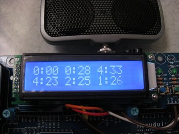
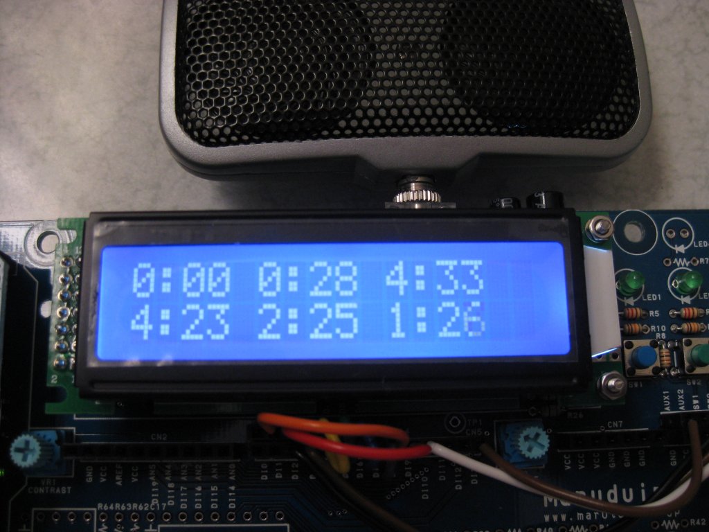
Maruduinoでラーメンタイマー、、、ただし6個いっぺんに作れます。 [アプリケーション]
※なんかイマイチ感がありありだったので、スケッチを修正しました。今度はいっぺんに6個までカップラーメンを作ることができます。
 いや、ほら、カップラーメンって全部3分と言うわけでなく、3分だったり、4分だったり、うどんは5分が多いかな。
逆に焼きそばは1分とか、もうまちまち。
一人なら問題無いけれど、多人数で一つのキッチンタイマーでは苦しすぎる。
で、5個6個いっぺんに計測可能なラーメンタイマーを作りましたヨ。
これでキッチンタイマーの奪い合いも無くなり、平和にラーメンをすすれますネ。
LCDの接続はスケッチをごらんいただくとして、スピーカー出力はDI13(DIGITAL13)をAUX1に接続します。2つのスイッチを使いますが、SW1はDI2、SW2はDI3に接続します。
※例の100円スピーカーを接続するのをお忘れなく。
※メロディ発生のスケッチはexamplesのdigitalのtoneMelodyから流用していますので、pitches.hをプロジェクトフォルダーにコピーして使ってください。
※色々と気になる点はありますが、まあ善しとしましょう。
※なんか気の抜けるネタばかりですいません。

 いや、ほら、カップラーメンって全部3分と言うわけでなく、3分だったり、4分だったり、うどんは5分が多いかな。
逆に焼きそばは1分とか、もうまちまち。
一人なら問題無いけれど、多人数で一つのキッチンタイマーでは苦しすぎる。
で、
これでキッチンタイマーの奪い合いも無くなり、平和にラーメンをすすれますネ。
LCDの接続はスケッチをごらんいただくとして、スピーカー出力はDI13(DIGITAL13)をAUX1に接続します。2つのスイッチを使いますが、SW1はDI2、SW2はDI3に接続します。
※例の100円スピーカーを接続するのをお忘れなく。
※メロディ発生のスケッチはexamplesのdigitalのtoneMelodyから流用していますので、pitches.hをプロジェクトフォルダーにコピーして使ってください。
※色々と気になる点はありますが、まあ善しとしましょう。
※なんか気の抜けるネタばかりですいません。
/*
  LiquidCrystal Library - Hello World

 Demonstrates the use a 16x2 LCD display.  The LiquidCrystal
 library works with all LCD displays that are compatible with the
 Hitachi HD44780 driver. There are many of them out there, and you
 can usually tell them by the 16-pin interface.

 This sketch prints "Hello World!" to the LCD
 and shows the time.

  The circuit:
 * LCD RS pin to digital pin 8
 * LCD Enable pin to digital pin 9
 * LCD D4 pin to digital pin 4
 * LCD D5 pin to digital pin 5
 * LCD D6 pin to digital pin 6
 * LCD D7 pin to digital pin 7

 * 10K resistor:
 * ends to +5V and ground

 Library originally added 18 Apr 2008
 by David A. Mellis
 library modified 5 Jul 2009
 by Limor Fried (http://www.ladyada.net)
 example added 9 Jul 2009
 by Tom Igoe
 modified 25 July 2009
 by David A. Mellis


 http://www.arduino.cc/en/Tutorial/LiquidCrystal
 */

// include the library code:
#include <LiquidCrystal.h>
#include "pitches.h"

int int0_count,int1_count;
unsigned char store_sw_status[3];  /*スイッチ状態の記録*/
/*SW1はDI2に接続し、割り込み0、SW2はDI3に接続し、割り込み1で処理する。*/
unsigned long guard1_time,guard2_time;
int timers;
struct RECORD
{
  int minutes;
  unsigned long end_time;
} rec[6];

const struct SCORE
{
  int note;
  int dura;
} score[] =
{
  {NOTE_G4,4},
  {NOTE_A4,4},
  {NOTE_B4,2},
  {NOTE_A4,4},
  {NOTE_G4,8},
  {0,8},
  {NOTE_G4,4},
  {NOTE_A4,4},
  {NOTE_B4,4},
  {NOTE_A4,4},
  {NOTE_G4,4},
  {NOTE_A4,1},
};

const struct POSITION
{
  int x;
  int y;
} pos[] =
{
  {0,0},
  {5,0},
  {10,0},
  {0,1},
  {5,1},
  {10,1},
};

// initialize the library with the numbers of the interface pins
LiquidCrystal lcd(8, 9, 4, 5, 6, 7);

void setup()
{
  lcd.begin(16, 2);
  for( int i = 0; i < sizeof(pos) / sizeof(pos[0]); i++ )
  {
    lcd.setCursor(pos[i].x,pos[i].y);
    lcd.print("0:00");
  }

  attachInterrupt(0, sw1_int_handler, RISING);
  attachInterrupt(1, sw2_int_handler, RISING);
}

void loop()
{
  int i;
  char buffer[16];
  static int count1,count2;

  for( i = 0; i < sizeof(pos) / sizeof(pos[0]); i++ )
  {
    /*表示位置の設定*/
    lcd.setCursor(pos[i].x,pos[i].y);

    if( rec[i].end_time != 0 )
    {
      if( rec[i].end_time <= millis() )
      {
        rec[i].minutes = 0;
        rec[i].end_time = 0;
        play_melody();
        lcd.print(millis2min(buffer,0));
      }
      else
        lcd.print(millis2min(buffer,rec[i].end_time - millis()));
    }
  }

  if( count1 != int0_count )  /*割り込みカウントと不一致が検出された時*/
  {
    count1 = int0_count;  /*更新*/

    /*レコードが空いているかの判断*/
    for( i = 0; i < sizeof(pos) / sizeof(pos[0]); i++ )
    {
      if( rec[ timers ].end_time == 0 ) break;
      if( ++timers >= sizeof(pos) / sizeof(pos[0]) ) timers = 0;
    }

    /*書き込み可能な場合*/
    if( i != sizeof(pos) / sizeof(pos[0]) )
    {
      rec[ timers ].minutes = rec[ timers ].minutes + 1;
      rec[ timers ].minutes %= 10;
      lcd.setCursor(pos[ timers ].x,pos[ timers ].y);
      lcd.print(millis2min(buffer,rec[ timers ].minutes * 60 * 1000UL));
    }
  }

  if( count2 != int1_count )  /*割り込みカウントと不一致が検出された時*/
  {
    count2 = int1_count;  /*更新*/

    /*レコードが空いているかの判断*/
    for( i = 0; i < sizeof(pos) / sizeof(pos[0]); i++ )
    {
      if( rec[ timers ].end_time == 0 ) break;
      if( ++timers >= sizeof(pos) / sizeof(pos[0]) ) timers = 0;
    }

    if( i != sizeof(pos) / sizeof(pos[0]) )
    {
      rec[ timers ].end_time = (rec[ timers ].minutes * 60 * 1000UL) + millis();
      if( ++timers >= sizeof(pos) / sizeof(pos[0]) ) timers = 0;  /*レコード番号の更新*/
    }
  }

  delay( 50 );  /*表示更新時間*/
}

char *millis2min( char *dest, unsigned long milli )
{
  int minute,second,temp;

  if( milli > 10 * 60 * 1000UL ) return 0;
  temp = (int)(milli / 1000UL);
  minute = temp / 60;
  second = temp % 60;

  dest[0] = (minute % 10) + '0';
  dest[1] = ':';
  dest[2] = (second / 10) + '0';
  dest[3] = (second % 10) + '0';
  dest[4] = '\0';

  return dest;
}

void play_melody()
{
  for (int thisNote = 0; thisNote < sizeof(score) / sizeof(score[0]); thisNote++)
  {
    int noteDuration = 1000/score[thisNote].dura;
    tone(13, score[thisNote].note,noteDuration);
    int pauseBetweenNotes = noteDuration * 1.30;
    delay(pauseBetweenNotes);
  }
}

void sw1_int_handler()
{
  if( millis() > guard1_time )  /*現在時刻がガードタイムを越した時のみ有効とする*/
  {
    int0_count++;  /*有効割り込み数*/
    guard1_time = millis() + 300UL;  /*不感帯時間の再設定*/
  }
}

void sw2_int_handler()
{
  if( millis() > guard2_time )  /*現在時刻がガードタイムを越した時のみ有効とする*/
  {
    int1_count++;  /*有効割り込み数*/
    guard2_time = millis() + 300UL;  /*不感帯時間の再設定*/
  }
}
ITRONプログラミング入門―H8マイコンとHOSで始める組み込み開発
- 作者: 濱原 和明
- 出版社/メーカー: オーム社
- 発売日: 2005/04/25
- メディア: 単行本
Prototyping Lab ―「作りながら考える」ためのArduino実践レシピ
- 作者: 小林 茂
- 出版社/メーカー: オライリージャパン
- 発売日: 2010/05/27
- メディア: 大型本
Maruduino(Arduino)で簡易的なストップウオッチの製作 またかよ編 [アプリケーション]
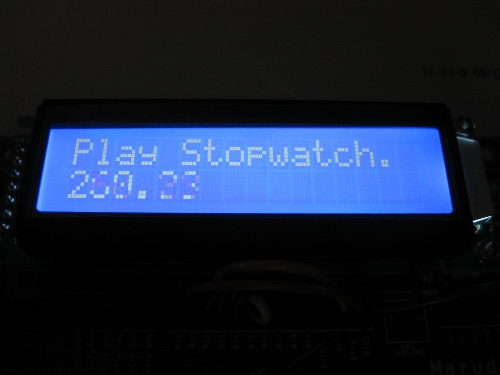 またかよぅ、と言った感じですが、、、
今までの方式で最大の問題は、計測時間が正確ではなかった点です。
今までの時間の取得は50ms+内部処理時間周期でSW1の状態を監視していたので、ワーストケースでは50ms+LCD表示など内部処理に掛かる時間だけ実際のスイッチの変化から遅れて計測がスタート、ストップしていました。
これを解消するためには、スイッチの変化に対して即座に反応し、計測の開始時間や終了時間を記憶する必要があります。
そこで、Arduinoのライブラリの中のattachInterruptと言う割り込みハンドラの登録機能を利用します。
これは、スイッチの状態の変化が検出されると通常のloop処理以外の流れ(コンテキスト)にマイコンの処理を切り替え、そこで必要な処理を行おうというものです。
必要な処理はユーザーが自分で作成し、登録します。
つまりこのユーザーが登録した別のコンテキストの先頭で変化を検出した時間を記録しておき、その値を計測時間として利用します。
また、同時にチャタリング?対策もここで行ってしまいます。
※厳密に言えばこの方法でもスイッチの変化から割り込みハンドラが起動して時間が記録されるまでに数十とか数百μsくらいの遅延は発生しているのですが、10msの精度から見れば十分に許容範囲内です。
ただしattachInterruptで利用できる端子は限定されており、DIGITAL2またはDIGITAL3のみです。その為、Hello Worldで利用しているLCD端子の移動が必要です。
以下に掲載するスケッチのコメント部にも具体的な割付を書きましたが、DIGITAL2をLCDの制御線から移動し、代わりにSW1からの入力に利用しています。
と言う訳で、スケッチをここに掲載しておきます。
/*
  LiquidCrystal Library - Hello World

 Demonstrates the use a 16x2 LCD display.  The LiquidCrystal
 library works with all LCD displays that are compatible with the
 Hitachi HD44780 driver. There are many of them out there, and you
 can usually tell them by the 16-pin interface.

 This sketch prints "Hello World!" to the LCD
 and shows the time.

  The circuit:
 * LCD RS pin to digital pin 8
 * LCD Enable pin to digital pin 9
 * LCD D4 pin to digital pin 4
 * LCD D5 pin to digital pin 5
 * LCD D6 pin to digital pin 6
 * LCD D7 pin to digital pin 7

 * 10K resistor:
 * ends to +5V and ground
 * wiper to LCD VO pin (pin 3)

 Library originally added 18 Apr 2008
 by David A. Mellis
 library modified 5 Jul 2009
 by Limor Fried (http://www.ladyada.net)
 example added 9 Jul 2009
 by Tom Igoe
 modified 25 July 2009
 by David A. Mellis


 http://www.arduino.cc/en/Tutorial/LiquidCrystal
 */

// include the library code:
#include <LiquidCrystal.h>
int mode;  /*初期状態は0(計測スタート待ち)*/
  /*初期状態→計測中→停止中→初期状態に戻る  の状態遷移を行う*/
int int_count;
unsigned long passed_time,latest_time;
unsigned long int_time,guard_time;

// initialize the library with the numbers of the interface pins
LiquidCrystal lcd(8, 9, 4, 5, 6, 7);

void setup() {
  // set up the LCD's number of rows and columns:
  lcd.begin(16, 2);
  // Print a message to the LCD.
  lcd.print("Play Stopwatch.");
  attachInterrupt(0, sw1_int_handler, RISING);
}

void loop() {
  static int count;

  if( count != int_count )  /*割り込みカウントと不一致が検出された時*/
  {
    count = int_count;  /*更新*/

    switch ( mode )
    {
      case 0 :  /*初期状態から計測中に遷移*/
        passed_time = int_time;  /*計測開始時刻*/
        mode = 1;
        break;
      case 1 :
        latest_time = int_time;  /*計測停止時刻*/
        mode = 2;
        break;
      default :
        lcd.setCursor(0, 1);
        lcd.print("                ");  /*表示クリア*/
        mode = 0;
        break;
    }
  }

  lcd.setCursor(0, 1);
  if( mode == 1 )
    lcd.print((double)(millis() - passed_time) / 1000.0);  /*0.1秒単位で出力*/
  else if( mode == 2 )
    lcd.print((double)(latest_time - passed_time) / 1000.0);  /*計測完了*/
  else
    lcd.print(0.0);  /*表示を0に戻す*/

  delay( 50 );  /*表示更新時間*/
}

void sw1_int_handler()
{
  if( millis() > guard_time )  /*現在時刻がガードタイムを越した時のみ有効とする*/
  {
    int_count++;  /*有効割り込み数*/
    int_time = millis();
    guard_time = int_time + 500UL;  /*不感帯時間の再設定*/
  }
}
Maruduino(Arduino)で簡易的なストップウオッチの製作2 [アプリケーション]
さて、前回は簡易的なストップウオッチを作成しました。機能的にだけではなく論理で簡易的にもやっているので、幾つかの問題があります。その一つは押下の検出にSW1の論理レベルを使っている事です。
もう一度スイッチの押下について考えてみます。
スイッチの情報を得る場合、2つの状態が考えられます。
1.今現在の状態の取得。つまり現在スイッチが押されているのか、それとも離されているのか?です。
2.スイッチの状態の変化の取得。つまり離されている状態から押された状態に変化したのか、それともその逆なのか?です。
実はこの2つの状態はよく組み合わせで使われます。スイッチを瞬間的に押された事を検出するなら2を、長押しを検出するなら1とかです。
前回のスケッチでは1の方法で検出をしていました。これはストップウオッチで1秒以上長押しされる事はあまり無い”だろう”と言う、あくまでもこちらの側の都合ですね。
で、今回は2の方法を実現してみます。
変化点を検出する為には、過去と現在の2つの状態が必要です。
スイッチが押された事を検出するなら、「過去は離されていたが、今見たら押されている!」と言う状態の検出です。
と言うわけで過去の状態を保存する変数と現在の状態を代入するbool型の変数の2つを用意してコーディングし直してみました。
この方法は、比較する論理レベルを逆にするとスイッチが離された事の検出に使えますし、bool型ではなく変数を整数型で複数ポートを一気に読み出し、代入を行うと、複数ポートの変化を論理だけで検出する事ができます。
※ITRON等で使う場合、変化点をXOR(排他的論理和)として検出し、その値をイベントフラグに代入すると、結構スマートな使い方が出来る。
/*
  LiquidCrystal Library - Hello World

 Demonstrates the use a 16x2 LCD display.  The LiquidCrystal
 library works with all LCD displays that are compatible with the
 Hitachi HD44780 driver. There are many of them out there, and you
 can usually tell them by the 16-pin interface.

 This sketch prints "Hello World!" to the LCD
 and shows the time.

  The circuit:
 * LCD RS pin to digital pin 12
 * LCD Enable pin to digital pin 11
 * LCD D4 pin to digital pin 5
 * LCD D5 pin to digital pin 4
 * LCD D6 pin to digital pin 3
 * LCD D7 pin to digital pin 2
 * 10K resistor:
 * ends to +5V and ground
 * wiper to LCD VO pin (pin 3)

 Library originally added 18 Apr 2008
 by David A. Mellis
 library modified 5 Jul 2009
 by Limor Fried (http://www.ladyada.net)
 example added 9 Jul 2009
 by Tom Igoe
 modified 25 July 2009
 by David A. Mellis


 http://www.arduino.cc/en/Tutorial/LiquidCrystal
 */

// include the library code:
#include <LiquidCrystal.h>
const int sw1 = 13;  /*スイッチ1の入力*/
int mode;  /*初期状態は0(計測スタート待ち)*/
  /*初期状態→計測中→停止中→初期状態に戻る  の状態遷移を行う*/
int ignore_time;
unsigned long passed_time,latest_time;
boolean kako,ima;  /*sw1の状態を過去の時点と今の時点で保存する変数*/

// initialize the library with the numbers of the interface pins
LiquidCrystal lcd(12, 11, 5, 4, 3, 2);

void setup() {
  pinMode( sw1, INPUT );
  // set up the LCD's number of rows and columns:
  lcd.begin(16, 2);
  // Print a message to the LCD.
  lcd.print("Play Stopwatch.");
  kako = (digitalRead( sw1 ) == HIGH) ? true : false;  /*初期化時に過去の値を保存して置く*/
}

void loop() {
  ima = (digitalRead( sw1 ) == HIGH) ? true : false;  /*今の状態を取得*/

  if( ignore_time == 0 && kako == false && ima == true )  /*つまり不感帯以外で過去に偽、今が真の時を探す*/
  {
    ignore_time = 20;  /*1秒の不感帯とする*/
    switch ( mode )
    {
      case 0 :  /*初期状態から計測中に遷移*/
        passed_time = millis();  /*計測開始時刻*/
        mode = 1;
        break;
      case 1 :
        latest_time =  millis();  /*計測停止時刻*/
        mode = 2;
        break;
      default :
        lcd.setCursor(0, 1);
        lcd.print("                ");  /*表示クリア*/
        mode = 0;
        break;
    }
  }
  kako = ima;  /*今の状態を過去に代入*/

  lcd.setCursor(0, 1);
  if( mode == 1 )
    lcd.print((double)(millis() - passed_time) / 1000.0);  /*0.1秒単位で出力*/
  else if( mode == 2 )
    lcd.print((double)(latest_time - passed_time) / 1000.0);  /*計測完了*/
  else
    lcd.print(0.0);  /*表示を0に戻す*/

  if( --ignore_time <= 0 ) ignore_time = 0;  /*スイッチを無視する時間の更新と上限*/

  delay( 50 );  /*表示更新時間*/
}
ITRONプログラミング入門―H8マイコンとHOSで始める組み込み開発
- 作者: 濱原 和明
- 出版社/メーカー: オーム社
- 発売日: 2005/04/25
- メディア: 単行本
Prototyping Lab ―「作りながら考える」ためのArduino実践レシピ
- 作者: 小林 茂
- 出版社/メーカー: オライリージャパン
- 発売日: 2010/05/27
- メディア: 大型本
Maruduino(Arduino)で簡易的なストップウオッチの製作1 [アプリケーション]
組み立て編でスイッチ、LED、LCDを実装しましたので、この辺で何か作ってみましょう。わりと判り易いと思われるストップウオッチです、、、既にArduinoの作例として何処かに登録されている様な気がしないでもないけれどネ。
機能としては一応100分の1秒表示。スイッチは一つ、その一つのスイッチで
1.計測待ち
2.計測
3.計測停止
の3状態を1~3に、また1に戻ると言った簡単な状態遷移で行います。
肝心の時間の計測には起動時からの時間をms単位で返すmillisライブラリを使用します。簡単ですから。
スイッチの押下の検出は自分でやらねばなりません。
ところでスイッチの入力となるといつも問題なるのがチャタリングでしょう。切り替えた時に接点がバウンス(はね返り)してONとOFFの状態が連続して表れるとか。
ですが、このストップウオッチのスイッチ入力に巨大なレバー式スイッチなど使いませんので、現実的にはバウンスが問題になる訳ではありません。
使用しているタクトスイッチは、上から押し込む事で離れていた導電ゴムの接点が押しつぶされる様に接触しますので、どっちかと言えば接触するかしないかの際での人間の指の状態とか、人によって長く押したり、短く押したりと言った時間的不確実性の方が問題です。
やっぱり何等かの不確実性を解消しないといけないのは事実ですので、もう少しこのストップウオッチにおけるスイッチの役目を考えてみると、
1.まず押された事を検出できれば良い、、、つまり離された事まで考慮する必要が無い。
2.ONとOFFが繰り返される事は時間のフィルターを用いる事で解消できる。
と言う訳で今回のストップウオッチにおけるスイッチ押下による状態遷移の条件として、前回の変化から一定以上の時間が経過している事。押下のみ検出とします。
LiquidCrystalのHell Worldを改造して以下の様なスケッチを書いて見ました。
しかし100分の1秒の精度は実に怪しいですね。
※一桁間違えたので修正(笑)
/*
  LiquidCrystal Library - Hello World

 Demonstrates the use a 16x2 LCD display.  The LiquidCrystal
 library works with all LCD displays that are compatible with the
 Hitachi HD44780 driver. There are many of them out there, and you
 can usually tell them by the 16-pin interface.

 This sketch prints "Hello World!" to the LCD
 and shows the time.

  The circuit:
 * LCD RS pin to digital pin 12
 * LCD Enable pin to digital pin 11
 * LCD D4 pin to digital pin 5
 * LCD D5 pin to digital pin 4
 * LCD D6 pin to digital pin 3
 * LCD D7 pin to digital pin 2
 * 10K resistor:
 * ends to +5V and ground
 * wiper to LCD VO pin (pin 3)

 Library originally added 18 Apr 2008
 by David A. Mellis
 library modified 5 Jul 2009
 by Limor Fried (http://www.ladyada.net)
 example added 9 Jul 2009
 by Tom Igoe
 modified 25 July 2009
 by David A. Mellis


 http://www.arduino.cc/en/Tutorial/LiquidCrystal
 */

// include the library code:
#include <LiquidCrystal.h>
const int sw1 = 13;  /*スイッチ1の入力*/
int mode;  /*初期状態は0(計測スタート待ち)*/
  /*初期状態→計測中→停止中→初期状態に戻る  の状態遷移を行う*/
int ignore_time;
unsigned long passed_time,latest_time;


// initialize the library with the numbers of the interface pins
LiquidCrystal lcd(12, 11, 5, 4, 3, 2);

void setup() {
  pinMode( sw1, INPUT );
  // set up the LCD's number of rows and columns:
  lcd.begin(16, 2);
  // Print a message to the LCD.
  lcd.print("Play Stopwatch.");
}

void loop() {
  if( ignore_time == 0 && digitalRead( sw1 ) == HIGH )  /*スイッチが押されるとHIGHとなる*/
  {
    ignore_time = 20;  /*1秒の不感帯とする*/
    switch ( mode )
    {
      case 0 :  /*初期状態から計測中に遷移*/
        passed_time = millis();  /*計測開始時刻*/
        mode = 1;
        break;
      case 1 :
        latest_time =  millis();  /*計測停止時刻*/
        mode = 2;
        break;
      default :
        lcd.setCursor(0, 1);
        lcd.print("                ");  /*表示クリア*/
        mode = 0;
        break;
    }
  }

  lcd.setCursor(0, 1);
  if( mode == 1 )
    lcd.print((double)(millis() - passed_time) / 1000.0);  /*0.1秒単位で出力*/
  else if( mode == 2 )
    lcd.print((double)(latest_time - passed_time) / 1000.0);  /*計測完了*/
  else
    lcd.print(0.0);  /*表示を0に戻す*/

  if( --ignore_time <= 0 ) ignore_time = 0;  /*スイッチを無視する時間の更新と上限*/

  delay( 50 );  /*表示更新時間*/
}
ITRONプログラミング入門―H8マイコンとHOSで始める組み込み開発
- 作者: 濱原 和明
- 出版社/メーカー: オーム社
- 発売日: 2005/04/25
- メディア: 単行本
 (Gakken Mook)")
大人の科学マガジン Vol.27(8ビットマイコン) (Gakken Mook)
- 作者: 大人の科学マガジン編集部
- 出版社/メーカー: 学習研究社
- 発売日: 2010/05/12
- メディア: ムック
Prototyping Lab ―「作りながら考える」ためのArduino実践レシピ
- 作者: 小林 茂
- 出版社/メーカー: オライリージャパン
- 発売日: 2010/05/27
- メディア: 大型本
超音波距離計の製作2 [アプリケーション]
 前回ブレッドボード上でプロトタイピングを行い、なんとか動かせる目処が付いたので、折角なので基板化してみました。回路は変更ありません。
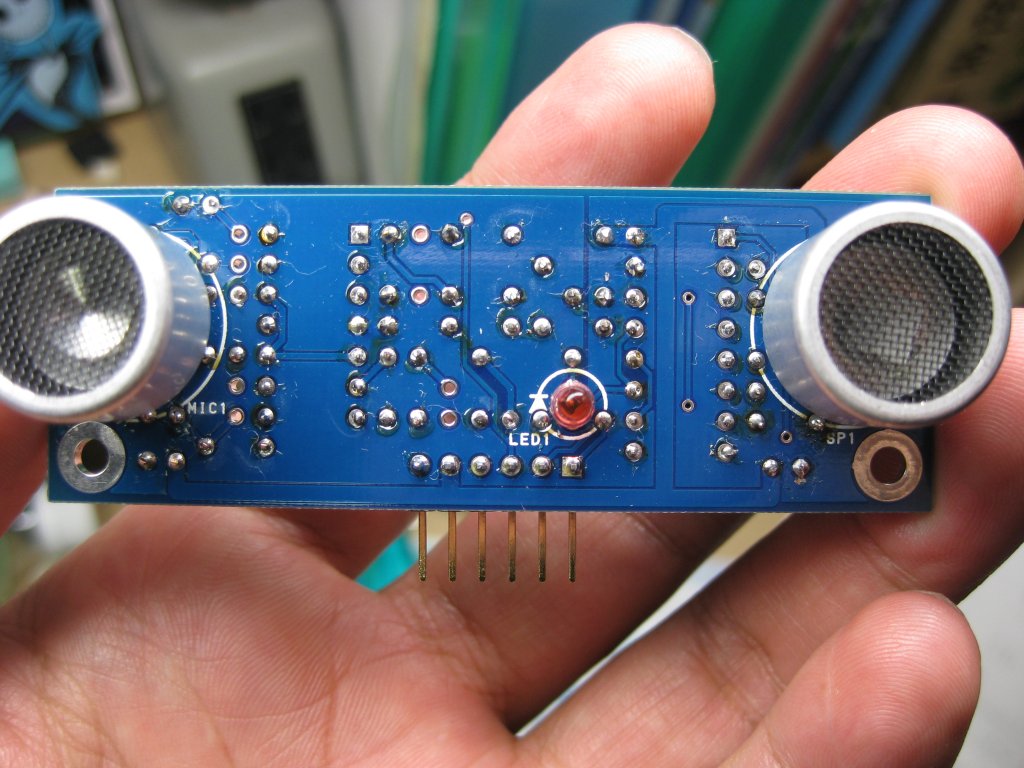 作成した基板の表側?です。スピーカー、マイク、LEDがこちらを見ています。
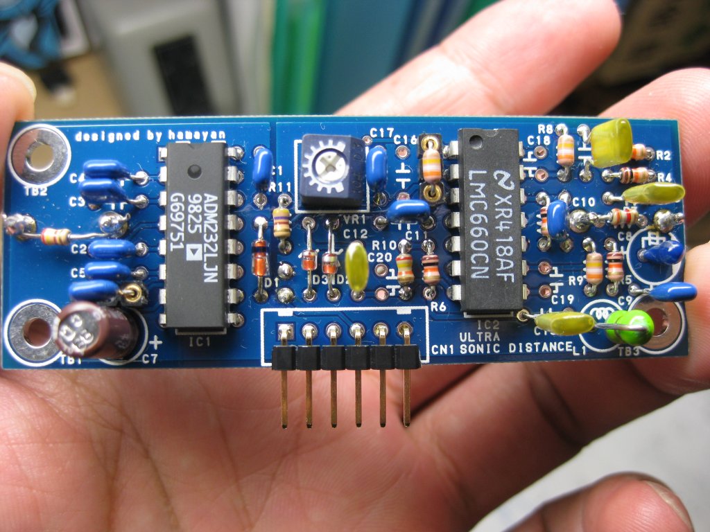 裏側です。リード部品を所狭しと搭載しています。スピーカーと反対側にこれらの部品を実装したからなんとか収まった様なものです。
実際にブレッドボード上でプロトタイピングしたので大体は上手く動くのですが、基板化する事により発生した問題なんてのもあります。
ブレッドボード上にスピーカーを載せた時は、スピーカーの固定はゆるゆるです。あの穴にズボっと挿すだけですから。
ところが基板上に半田付けしてしまうとかなりかっちり固定される事となります。
超音波を発している時間は極短い時間ですし、周波数も40KHzと可聴領域の遥か上です。それなのに、なにやら音がポツッ!、ポツッ!と聞こえてきます。
そうです、どうも超音波を駆動した時、スピーカー自身がそのショックで振動してしまうようです。この振動が剛性のある基板を経由してマイク側に伝わるものですから、受信側は大変な事になってしまいます。
※耳にはっきりと聞き取れる位の音なので、可聴領域の周波数だとしても、その振動の継続時間がかなり長くなっていると思われ、これがゲート時間を超えています。
対策は色々あると思いますが、最も良いのはスピーカー側の固定をフローティングする事でしょう。但し機構的に難しいので妥協として出力レベルを押さえる事とします。
ADM3202の出力には最低300Ωの抵抗が入っています。これは短絡に対する保護だと思われますが、出力抵抗が300Ωだと考えれば、抵抗で分圧する事でスピーカーの入力を小さくできます。
今は240Ωの抵抗をスピーカーの2つの端子間に入れています。これだと2m弱位の測定距離となる様です。
まあ、まだまだカットアンドトライが必要みたいですが、一応完成と言う事で。

Prototyping Lab ―「作りながら考える」ためのArduino実践レシピ
- 作者: 小林 茂
- 出版社/メーカー: オライリージャパン
- 発売日: 2010/05/27
- メディア: 大型本

Making Things Talk ―Arduinoで作る「会話」するモノたち
- 作者: Tom Igoe
- 出版社/メーカー: オライリージャパン
- 発売日: 2008/11/17
- メディア: 大型本
大人の科学マガジン Vol.27(8ビットマイコン) (Gakken Mook)
- 作者: 大人の科学マガジン編集部
- 出版社/メーカー: 学習研究社
- 発売日: 2010/05/12
- メディア: ムック
超音波距離計の製作1 [アプリケーション]
※勿論これは普通にArduinoでも実験可能です!。是非お試しを。
 超音波距離計は、40KHzの超音波領域の音をスピーカーから発し、対象物に当たって帰って来た音をマイクで拾い、往復に掛かった時間から対象物までの距離を計算すると言う、わりと簡単な原理で動いています。
秋月で発売されている超音波距離計は、タイマーICで40KHzを生成してスピーカーで出し、マイクで拾った音を増幅して簡単なバンドパスフィルターを通して一定のレベルとの比較出力を時間を換算しているロジックに入れて距離を出し、7セグメントLEDにて表示をしています。
なかなか良く考えられた回路だと思います。
翻ってArduinoでそれをやろうとした時、勿論特別にタイマーICを用意する必要も、時間を計るロジックICを用意する必要も無く、全てはArduinoのAVRマイコンの中にあります。
なので超音波距離計を作る残りの要素は極僅かですね。
超音波スピーカーをドライブする回路と、超音波スピーカー、超音波マイクに増幅回路、バンドパスフィルター、レベル比較器、表示器だけです。
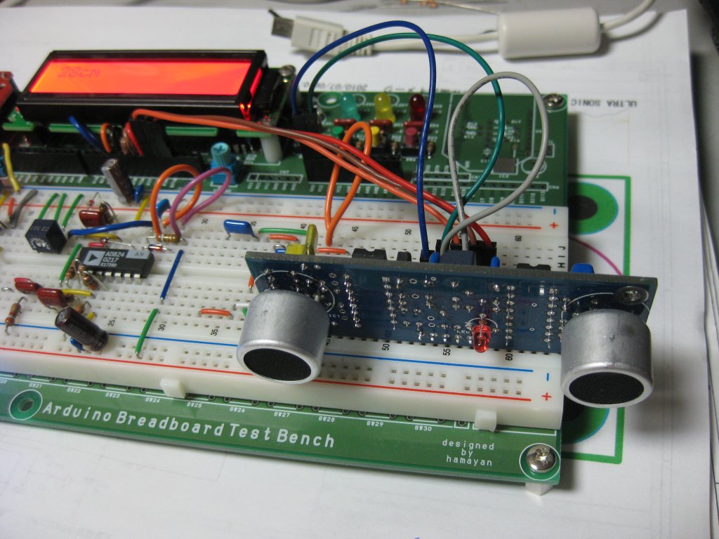
この位の回路なら十分ブレッドボード上に構成可能です。それがこの記事の冒頭の写真となっています。
回路図はこれです。拡張子をpdfに戻してください。
また、スケッチは簡単ですが以下の内容で可能です。
※Maruduinoのプロトタイプ基板で作成している為、若干発売中の基板とはポートが異なります。

 超音波距離計は、40KHzの超音波領域の音をスピーカーから発し、対象物に当たって帰って来た音をマイクで拾い、往復に掛かった時間から対象物までの距離を計算すると言う、わりと簡単な原理で動いています。
秋月で発売されている超音波距離計は、タイマーICで40KHzを生成してスピーカーで出し、マイクで拾った音を増幅して簡単なバンドパスフィルターを通して一定のレベルとの比較出力を時間を換算しているロジックに入れて距離を出し、7セグメントLEDにて表示をしています。
なかなか良く考えられた回路だと思います。
翻ってArduinoでそれをやろうとした時、勿論特別にタイマーICを用意する必要も、時間を計るロジックICを用意する必要も無く、全てはArduinoのAVRマイコンの中にあります。
なので超音波距離計を作る残りの要素は極僅かですね。
超音波スピーカーをドライブする回路と、超音波スピーカー、超音波マイクに増幅回路、バンドパスフィルター、レベル比較器、表示器だけです。
この位の回路なら十分ブレッドボード上に構成可能です。それがこの記事の冒頭の写真となっています。
回路図はこれです。拡張子をpdfに戻してください。
また、スケッチは簡単ですが以下の内容で可能です。
※Maruduinoのプロトタイプ基板で作成している為、若干発売中の基板とはポートが異なります。
/***********************************************************************/
/* ultra sonic distance meter                                          */
/*                                               designed by hamayan   */
/*                                               Copyright(C) hamayan  */
/***********************************************************************/
#include <LiquidCrystal.h>
#include <avr/io.h>
#include <avr/interrupt.h>

/*************************************************************************/
/* defines                                                               */
/*************************************************************************/
#define  AREF     0
#define  NOT_GND  1
#define  DI13     2
#define  DI12     3
#define  DI11     4
#define  DI10     5
#define  DI9      6
#define  DI8      7
#define  DI7      8
#define  DI6      9
#define  DI5      10
#define  DI4      11
#define  DI3      12
#define  DI2      13
#define  DI1
#define  DI0
#define  AN0      14
#define  AN1      15
#define  AN2      16
#define  AN3      17
#define  AN4      18
#define  AN5      19
#define  PWM11    DI4
#define  PWM10    DI5
#define  PWM9     DI6
#define  PWM6     DI9
#define  PWM5     DI10
#define  PWM3     DI12

/*************************************************************************/
/*  global parameter                                                     */
/*************************************************************************/
#define  UltraSonicPin  PWM6
LiquidCrystal lcd(DI2, DI3, DI4, DI5, DI6, DI7);

/*************************************************************************/
/*  prototype                                                            */
/*************************************************************************/

/*************************************************************************/
/*  timer1 output compare match a int handler                            */
/*************************************************************************/
SIGNAL( TIMER1_COMPA_vect )
{
}

/*************************************************************************/
/*  setup                                                                */
/*************************************************************************/
void setup()
{
  lcd.begin(16,2);
  lcd.clear();
  lcd.print( "designed by" );
  lcd.setCursor(0,1);
  lcd.print( "  hamayan." );
  pinMode( DI8, INPUT );
  pinMode( DI10, OUTPUT );
  digitalWrite( DI10, LOW );
}

/*************************************************************************/
/*  main loop                                                            */
/*************************************************************************/
void loop()
{
  digitalWrite( DI10, HIGH );
  tone( UltraSonicPin, 40000 );
  unsigned long startMicro = micros();
//  delayMicroseconds( 500 / 8 );
  delayMicroseconds( 250 / 8 );
  noTone( UltraSonicPin );
//  delayMicroseconds( 500 / 8 );
  delayMicroseconds( 750 / 8 );
  digitalWrite( DI10, LOW );
  delayMicroseconds( 500 / 8 );
  unsigned long endMicro = startMicro;
  while( digitalRead( DI8 ) == LOW )
  {
    endMicro = micros();
    if( (endMicro - startMicro) > 20 * 1000UL ) break;
  }

  unsigned long distance;
  if( (endMicro - startMicro) < 20 * 1000UL )
  {
    distance = ((340 * (endMicro - startMicro)) / 10000UL) / 2;
  }
  else
  {
    distance = 999;
  }

  lcd.clear();
  lcd.print( distance );
  lcd.print( "cm" );

  delay( 500 );
}
Prototyping Lab ―「作りながら考える」ためのArduino実践レシピ
- 作者: 小林 茂
- 出版社/メーカー: オライリージャパン
- 発売日: 2010/05/27
- メディア: 大型本
- 作者: Theodore Gray
- 出版社/メーカー: オライリージャパン
- 発売日: 2010/05/24
- メディア: 大型本


